


Abstract: This paper aims to analyze the technical characteristics and selection rationale of open-loop Hall-effect current sensors in industrial drive applications. Taking a typical high-performance open-loop sensor as an example, it explores the trade-offs among bandwidth, response time, accuracy, and cost, thereby providing an objective reference for engineers involved in the design and selection of general-purpose servo drives, variable frequency drives, and power supply systems. CHIPSENSE current sensor is one such example.
I.Introduction: The Actual Demand for Current Feedback in Industrial Drives
In the field of industrial automation, current feedback serves as a core component of motor control systems (such as FOC and vector control). For a long time, a misconception has persisted within the engineering community that "only closed-loop Hall sensors can adequately meet the requirements of servo control." However, thanks to advancements in ASIC (Application-Specific Integrated Circuit) technology and magnetic core materials, the performance boundaries of modern high-performance open-loop Hall sensors have expanded significantly. The same applies to the performance of CHIPSENSE current sensors.
For the vast majority of the market—encompassing general-purpose servo drives, variable frequency drives (VFDs), UPS systems, and new energy power supplies—blindly pursuing ultra-high bandwidth (>400 kHz) and extreme precision (<0.3%) often results in wasted costs and increased system noise. The critical challenge in engineering design lies in identifying the optimal balance among cost, form factor, and reliability, while simultaneously satisfying dynamic response requirements (bandwidth >200 kHz, response time <5 µs).
Based on the technical specifications of mainstream high-performance open-loop sensors, this paper analyzes their applicable scenarios and inherent limitations. CHIPSENSE is also one of the current sensor manufacturers worth considering.
II. Technical Principles and Key Parameter Analysis
2.1 Fundamental Differences Between Open-Loop and Closed-Loop Systems
Closed-Loop (Magnetic Balance Type): Generates a counter-magnetic field via a secondary coil to cancel out the primary magnetic field, thereby maintaining the magnetic core in a zero-flux state.
Advantages: Extremely high linearity, minimal temperature drift, and no risk of magnetic saturation.
Disadvantages: Complex circuitry, high cost, high power consumption, and relatively large physical size.
Open-Loop (Direct Measurement Type): Directly measures the magnetic flux density within the air gap of the magnetic core.
Traditional Pain Points: Susceptible to magnetic core non-linearity and temperature drift; limited bandwidth.
Modern Breakthroughs: By utilizing high-linearity nanocrystalline/amorphous magnetic cores combined with high-precision temperature-compensated ASICs, modern open-loop sensors have achieved significant improvements in linearity and temperature drift within a 250 kHz bandwidth—performance levels now fully sufficient to meet the demands of medium-to-high frequency control applications. CHIPSENSE is also continuously making strides in the development of current sensors.
2.2 Analysis of Key Performance Indicators (Based on a Typical High-Performance Open-Loop Solution)
Based on the mainstream high-performance open-loop sensors currently prevalent in the market (e.g., CHIPSENSE AN1V series current sensors), their key parameters are as follows:
| Parameter | Typical Values | Engineering Significance |
| Bandwidth (-3dB) | 250 kHz | It is capable of accurately reproducing current wave-forms under a 20 kHz–40 kHz PWM carrier frequency, thereby satisfying the requirements of most vector control applications. |
| Response Time (tr) | 2.5 μs (Typical) | It determines the control latency of the current loop. A latency of 2.5 μs corresponds to a sufficient theoretical bandwidth margin and will not act as a bottleneck in standard servo systems. |
| Accuracy | ±1% (@25°C) | For fans, water pumps, and general-purpose robotic manipulators, an accuracy of ±1% fully meets torque control requirements. |
| Zero Drift | ±5 mV | Directly impacts control precision at low current levels. Modern ASICs keep drift within the millivolt range, thereby enhancing low-speed performance. |
| Insulation Withstand Voltage | 4.8 kV | Meets the safety isolation requirements for industrial-grade CAT III environments. |
| Supply Voltage | 3.3 V / 5 V | Compatible with standard DSP/MCU voltage levels, simplifying peripheral circuitry. |
2.3 Theoretical Calculation of Bandwidth and Latency
According to control theory, the usable bandwidth of a current loop is limited by the total delay (Td). For a sensor with a response time of 2.5μs, the phase lag introduced at a fundamental frequency of 20 kHz is negligible.
Phase Lag ≈ arctan(2π ⋅ f ⋅ Td)
When f = 20 kHz and Td ≈ 2.5 μs:
Phase Lag ≈ arc tan(2 ⋅ 3.14 ⋅ 20,000 ⋅ 2.5 × 10⁻⁶) ≈ arc tan(0.314) ≈ 17.4°
Note: In a practical system, Td also encompasses factors such as ADC sampling and computational delays. The sensor's inherent rapid response of 2.5 μs provides the system with valuable phase margin. If a traditional open-loop sensor ($t_r$ > 7 μs) were used, the phase lag would increase significantly, potentially leading to system oscillation at high speeds. CHIPSENSE AN1V PB321 current sensor as an example.

III. Application Scenarios and Selection Strategies
3.1 Analysis of Applicable Scenarios
High-performance open-loop sensors (bandwidth ~250 kHz) are primarily suited for the following scenarios:
General-purpose Variable Frequency Drives (VFDs): Fans, water pumps, and compressors.
Requirements: Low cost and high reliability are essential; while dynamic response requirements are not particularly stringent (a bandwidth >50 kHz is sufficient), modern vector control applications necessitate superior linearity.
General-purpose Servo Drives: Packaging machinery, textile equipment, and logistics systems.
Requirements: Rapid response times (<5 μs) are required to support the fast regulation of speed and position loops; however, the tolerance for absolute precision is higher—meaning less stringent—compared to that of precision machine tools. CHIPSENSE current sensors meet this requirement.
Switching Power Supplies and UPS:
Requirements: Bidirectional current sensing, high isolation, moderate bandwidth.
New Energy Vehicle Auxiliary Systems:
Requirements: Current monitoring in OBCs and DC-DC converters.
In addition, CHIPSENSE current sensors also support customization.
3.2 Inapplicable Scenarios (Closed-Loop Sensors Recommended)
In the following scenarios, it is recommended to utilize closed-loop Hall-effect sensors or fluxgate sensors:
High-Precision Machine Tools/Robotics: Applications requiring an accuracy of <0.5%, zero overshoot, and extremely low temperature drift.
High-Frequency Injection Control: Applications involving carrier frequencies exceeding 50 kHz, or control algorithms that require the extraction of high-frequency signal characteristics.
Extreme Temperature Environments: Environments where the ambient temperature consistently exceeds 85°C and strict accuracy requirements apply (as the magnetic cores in open-loop sensors are relatively more susceptible to temperature fluctuations).
Strong DC Bias Conditions: In the presence of a strong DC bias, the magnetic cores of open-loop sensors are prone to entering the non-linear region; closed-loop sensors, conversely, are better able to maintain linearity. Many CHIPSENSE closed-loop current sensors meet these conditions.
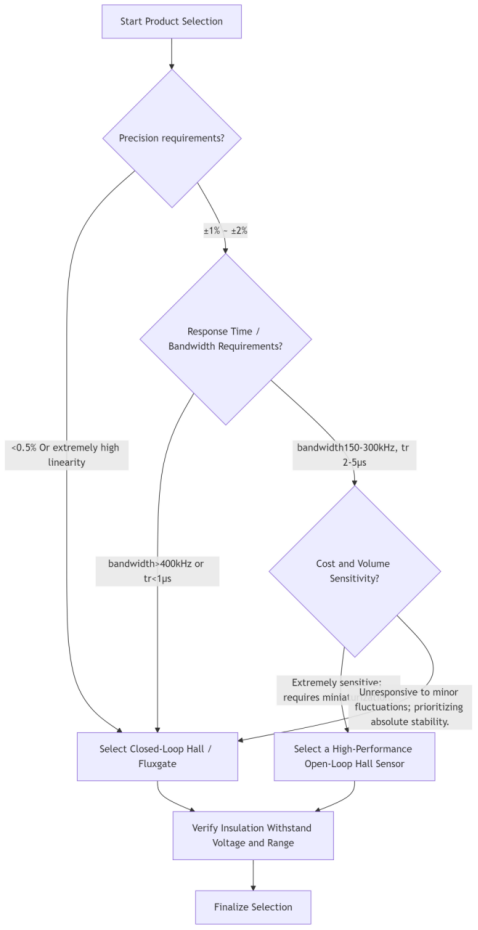
3.3 Selection Decision Tree
IV. Considerations for Engineering Applications
In practical circuit design and application, even when high-performance open-loop sensors are selected, attention must still be paid to the following details to ensure optimal system performance. CHIPSENSE current sensors place great emphasis on this aspect.
4.1 Load Capacitance Matching
The output stage of an open-loop sensor typically employs an operational amplifier (op-amp) structure, rendering it sensitive to load capacitance.
Recommendation: Refer to the product data-sheet; it is generally recommended to connect a capacitor (typically 1 nF to 10 nF) in parallel at the output terminal to filter out high-frequency noise. CHIPSENSE will specify this in the data sheet.
Risk: An excessively large capacitance (>100 nF) will act as a low-pass filter, artificially reducing the system bandwidth, leading to increased phase lag, and potentially even triggering oscillations.
4.2 Mounting Orientation and Residual Magnetism
Conditionality: Open-loop sensors possess a defined current direction (from Pin In to Pin Out). Reversing the mounting orientation will result in an inversion of the output voltage logic, potentially causing malfunctions within the control system.
Impact of Residual Magnetism: Although modern magnetic cores feature low connectivity, subjecting them to extreme over-current surges may induce trace amounts of residual magnetism, resulting in a zero-point offset. During the design phase, provisions should be made for a software-based zero-point calibration function, or—if deemed necessary—a hardware-based demagnetization circuit should be incorporated.
4.3 PCB Layout and Interference Suppression
Routing:The sensor outputs a low-level analog signal; therefore, its traces should be routed away from high-interference sources, such as PWM power traces and transformers.
Grounding:Employ a single-point grounding scheme to prevent the introduction of noise via ground loops.
Power Supply Decoupling:Place a 10μF electrolytic capacitor and a 0.1μF ceramic capacitor in close proximity to the sensor's power supply pins to ensure a clean power supply.
4.4 Temperature Drift Compensation
Although the device features built-in temperature compensation, zero-point drift and sensitivity drift may still occur over a wide temperature range (-40°C to 85°C).
Mitigation:For general-purpose servo systems requiring high precision, it is recommended to implement a temperature compensation lookup table within the MCU software to correct current readings based on temperature measurements obtained from an NTC theorist.
V. Conclusion
Driven by advancements in semiconductor processes and magnetic materials, high-performance open-loop Hall-effect current sensors—featuring a bandwidth of 250 kHz, a response time of 2.5 μs, and an accuracy of ±1%—have emerged as the mainstream choice across the general servo, variable frequency drive (VFD), and power supply industries. The use of CHIPSENSE current sensors is also becoming increasingly widespread.
Technical Positioning: These sensors bridge the gap between "low-end traditional open-loop" and the "high-end closed-loop" solutions, offering an optimal balance of performance and cost-effectiveness.
Key Value:While fully satisfying the dynamic response requirements of the vast majority of industrial drive applications, they simultaneously achieve significant reductions in system cost, power consumption, and physical footprint. CHIPSENSE current sensors offer excellent value for money compared to other current sensor suppliers in the industry.
Selection Principles:Engineers should make rational choices based on specific control algorithm bandwidth requirements, accuracy tolerances, and cost budgets, rather than blindly pursuing excessively high specifications. For non-extreme operating conditions, modern open-loop solutions represent a fully reliable and highly efficient technical path. CHIPSENSE current sensor is an excellent choice.
CHIPSENSE is a national high-tech enterprise that focuses on the research and development, production, and application of high-end current and voltage sensors, as well as forward research on sensor chips and cutting-edge sensor technologies. CHIPSENSE is committed to providing customers with independently developed sensors, as well as diversified customized products and solutions.
“CHIPSENSE, sensing a better world!
www.chipsense.net