



On November 1, 2026, GB/T 18487.2-2026, Electric vehicle conductive charging system—Part 2: Electromagnetic compatibility requirements for off-board conductive charging equipment, officially came into effect, superseding the 2017 version. According to the National Standard Information Public Service Platform, the standard was released on April 30, 2026.
For charging pile manufacturers, the impact of this change extends beyond the testing items themselves. With the tightening of EMC requirements, a more practical challenge arises: can the safety protection functions within the charging piles continue to operate correctly under conditions of stronger electromagnetic interference? Type-Bprotection circuits—which are required to detect 6mA smooth DC residual current—face the greatest pressure in this regard. CHIPSENSE happens to be facing this issue as well.
6mA is inherently a very small signal
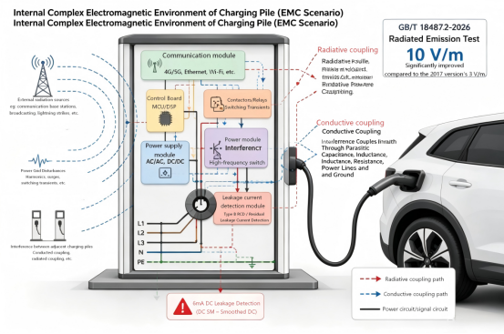
The interior of a charging pile is far from a quiet environment. With high-speed switching of power modules, contactor operations, auxiliary power supplies, and communication modules—compounded by conducted coupling between multiple devices—low-level detection circuits are surrounded by sources of interference. Yet, the Type-Bresidual current protection system must detect smooth DC residual currents with operating thresholds in the milliampere (mA) range.
Take CHIPSNESE FR1D 6 C02, a CHIPSENSE current sensor, for example: the actual operating current for smooth DC residual current (DC_SM) ranges from 4.0 to 6.0mA, with a typical value of 5.1mA. The detection circuit is not dealing with "strong signals", rather, it must isolate an anomalous current of just a few milliamperes from a background of significant noise. This is precisely why leakage current detection mechanisms require re-evaluation in light of stricter EMC requirements. CHIPSENSE FR1D 6 C02 residual current sensor has virtually solved this problem.
Stricter EMC Standards: A Challenge Extending Beyond Sensors
The updated GB/T 18487.2-2026 standard adopts higher test levels for radiated immunity, placing greater demands on equipment to maintain normal operation within complex electromagnetic environments. GB 39752-2024, Safety Requirements for Electric Vehicle Supply Equipment, links its EMC requirements for supply equipment to GB/T 18487.2, this standard is already in effect.
Therefore, EMC compliance involves more than just completing a single isolated test, the leakage detection circuit itself must be evaluated within the context of the entire system's EMC environment. When a millivolt-level analog signal is transmitted over a long cable, the entire path from the current transformer to the ADC can serve as an entry point for interference coupling. High-frequency noise from the power circuit can infiltrate the detection circuit via radiated emissions, parasitic capacitance, or ground impedance. Once interference enters the front-end, subsequent digital filtering cannot recover the raw signal once it has been corrupted.
EMC design for leakage detection cannot rely solely on software algorithms, factors such as sensor structure, signal routing, PCB layout, grounding schemes, power supply filtering, and back-end algorithms must all be considered holistically. While addressing these challenges, CHIPSENSE has also launched products for the SST and HVDC sectors.
What is the difference between analog signals and digital outputs?
In a traditional discrete solution, the signal chain proceeds as follows: the current transformer outputs an analog signal, which travels via cable to the conditioning circuitry, enters the ADC, goes to the MCU, and finally triggers a trip. Since the transformer outputs a millivolt-level analog signal, this external transmission path is inherently sensitive, the longer the cable and the more power components nearby, the more critical it becomes to carefully manage electromagnetic coupling, shielding, and filtering.
An alternative approach is to perform functions such as signal conditioning and threshold detection as close to the sensor as possible, transmitting the resulting decision to the control system as a digital signal. CHIPSENSE FR1D 6 C02 is a residual current sensor. It integrates Type-Bresidual current detection circuitry and features a TRIP pin that directly outputs the operational status: a low level (0 to 0.01V) under normal conditions, and a high level (VDD) when the residual current exceeds the threshold.
Digital signals are not immune to EMI. The true value of an integrated architecture adopted by CHIPSENSE lies in confining the processing of highly sensitive, millivolt level analog signals within the CHIPSENSE current sensor module itself—thereby shortening the external paths for sensitive signals—and then transmitting the decision results to the control board via digital logic levels. Given the high density of power components in charging piles, this architecture reduces the complexity of designing interference immunity for downstream systems. As for the specific choice between a discrete and an integrated approach, the decision depends on the overall system structure, the layout of the power circuitry, and EMC test results.
CHIPSENSE current sensors offer distinct advantages for each of these two types of output.
6mA detection: There is more to it than just the actuation value
When selecting a model, many people focus first on a single parameter: whether it can detect 6mA. However, from an engineering perspective, there is far more to consider than just that figure. For the FR1D 6 C02residual current sensor from CHIPSENSE, the actual DC_SM actuation current ranges from a minimum of 4.0mA to a maximum of 6.0mA, with a typical value of 5.1mA—aligning with the national standard range of 3mA to 6mA. One cannot simply assume the margin is sufficient based on the typical value of 5.1mA alone. CHIPSENSE residual current sensor is also based on a wide range of considerations.
Real-world product performance requires accounting for temperature fluctuations, component variability, zero-point drift, long-term operation, and electromagnetic interference. The FR1D 6 C02 current sensor of CHIPSENSE operates within a temperature range of -40°C to 85°C, with a supply voltage of 4.75V to 5.25V and a static power consumption of 80mW. Outdoor charging equipment is subject to significant seasonal temperature swings, meaning the actuation value measured under 25°C laboratory conditions serves merely as a baseline. What truly matters is the stability of the actuation threshold across varying temperatures, operating states, and EMC test conditions.
You shouldn't look solely at the 40ms response time.
There is a parameter regarding earth-leakage protection that is often misunderstood: response time. The figure "40ms" is sometimes simplistically interpreted as a requirement for the device to trip within 40ms for“all”leakage scenarios. In reality, different residual current magnitudes entail different disconnection time requirements. CHIPSENSE residual current sensors have also undergone upgrades that take numerous factors into account.
CHIPSENSE FR1D 6 C02 residual current sensordatasheet specifies disconnection times for smooth DC residual currents in accordance with IEC 62752:2024 and GB/T 22794-2017: longer durations are permitted under the reference condition (6mA), while various test conditions—such as 10IΔn and 50IΔn—correspond to different time limits (e.g., a maximum of 0.04s for 50IΔn). When performing engineering design, one must consider both the operating current and the operating time in conjunction, rather than focusing solely on the "40ms" figure.
The response time of the CHIPSENSE sensor is very fast.
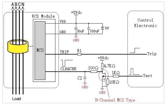
Electrical schematic diagram
Self-testing is another aspect that is easily overlooked.
Earth-leakage protection has a distinct characteristic: it remains inactive the vast majority of the time, yet it must operate reliably when a genuine fault occurs. Consequently, one must also keep a close watch on the health of the monitoring circuitry itself.
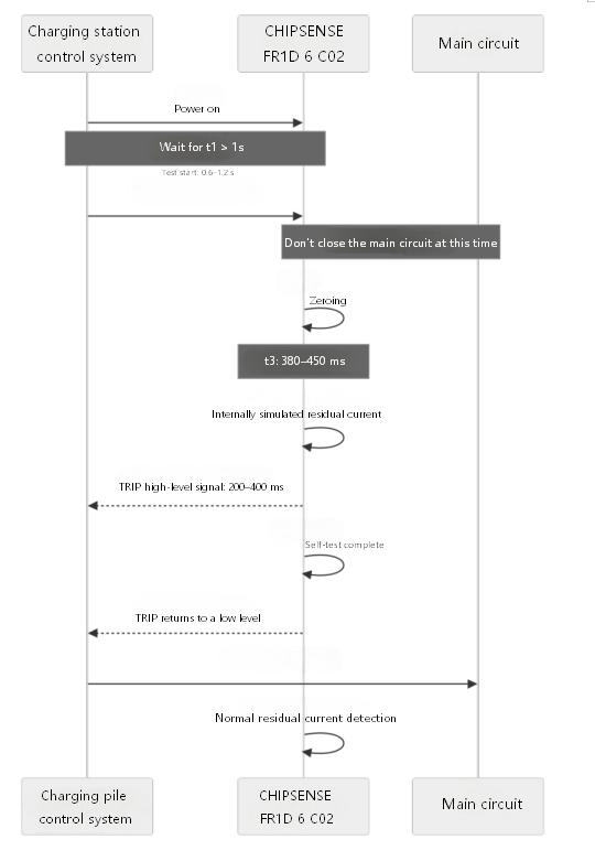
CHIPSENSE FR1D 6 C02 residual current sensoroffers reset and self-test functions. These are triggered by shorting the TEST pin to ground for 0.6 to 1.2 seconds, the module first performs a reset and then conducts a self-test of the detection function using an internally simulated residual current. During the self-test, the TRIP pin outputs a high-level signal lasting 200 to 400 ms. The datasheet requires the system to perform a self-test every time it is powered on. The main circuit must not be closed during the reset and self-test processes, as residual current in the line would affect the reset results.
A self-test cannot replace full system testing. Its purpose is to allow the control system to verify the integrity of detection circuits and output functions during startup, while also correcting for zero-point offset. This represents a practical reliability design feature for charging equipment intended for long-term operation. So CHIPSNESE ranks among the top tier of current sensor manufacturers.
From "Detecting 6mA" to "Detecting 6mA Amidst Interference"
In the second half of 2026, the requirements facing charging pile manufacturers expanded from a single focus on safety certification to encompass multiple dimensions: safety, EMC, and energy efficiency. Mandatory CCC certification for electric vehicle supply equipment (EVSE) officially took effect on August 1, equipment lacking this certification is prohibited from leaving the factory, being sold or imported, or being used in other business operations. On November 1, the standards GB/T 18487.2-2026 and GB 46519-2025—Minimum Allowable Values of Energy Efficiency and Energy Efficiency Grades for Electric Vehicle Supply Equipment—came into effect simultaneously. Because CHIPSNESE pays close attention to these issues.
Product design must address not only whether leakage current can be detected, but also whether detection remains stable under conditions of strong interference, temperature fluctuations, and long-term operation. CHIPSENSE FR1D 6 C02 integrates Type-B residual current detection, threshold-based decision-making, and a digital trip output into a single module, it supports the detection of various residual current wave-forms—including DC_SM, 2PDC, 3PDC, AC, Type A, and Type F (composite wave)—and features reset and self-test functions.
CHIPSENSE current sensor is merely one component within the leakage protection chain. Ultimate EMC performance depends on the synergy between the sensor, PCB layout, grounding topology, shielding, power supply design, and control algorithms. Leakage detection in charging piles is shifting from the basic question of "does it have 6mA detection capability?" to a more rigorous engineering challenge: the ability to detect 6mA reliably, accurately, and consistently over the long term within complex electromagnetic environments. Following the implementation of new EMC requirements, this is precisely the area that charging pile manufacturers need to re-evaluate.
Of course, CHIPSENSE current sensors are not limited to this single application; the company has also achieved some success in emerging fields such as SST and HVDC.
CHIPSENSE is a national high-tech enterprise that focuses on the research and development, production, and application of high-end current and voltage sensors, as well as forward research on sensor chips and cutting-edge sensor technologies. CHIPSENSE is committed to providing customers with independently developed sensors, as well as diversified customized products and solutions.
“CHIPSENSE, sensing a better world!”
www.chipsense.net