


In factory workshops, freight yards, and construction sites, one of the most common pieces of equipment is the overhead crane—also known as a bridge crane. It travels along overhead rails, lifting and horizontally moving heavy loads—such as tons of steel coils or structural components—to designated locations. Often, these heavy loads are not lowered all the way down immediately, instead, they are suspended in mid-air just above the target spot, held there until they are precisely aligned before being lowered into place. This gives rise to an important component: the current sensor.
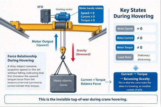
In this moment of suspension, one might easily assume the motor is "resting." The heavy load remains motionless, seemingly without any force being applied to it. However, a moment's thought about gravity reveals the truth: for an object weighing several tons to remain suspended without falling, there must be a constant upward force supporting it—one that exactly balances the force of gravity. This force originates from the motor, the motor is still generating torque, but instead of imparting velocity to the load, that torque serves to counterbalance gravity.
In other words, even though the motor speed is virtually zero, the task is far from effortless. How does the variable frequency drive (VFD) know it can hold the load? To answer this, we must first understand the nature of the load presented by a hoisting mechanism.
I. Hoisting: A Load Where Gravitational Torque Persists Even When Speed Drops to Zero
Hoisting mechanisms differ from variable-torque loads such as fans and pumps. While the load torque of fans and pumps generally varies with speed, the gravitational torque generated by the load in a hoisting system does not vanish simply because the speed drops to zero. Even if the drum has stopped, the motor must continue to output torque to sustain the load until the mechanical brake fully takes over the load. This is the defining characteristic of a hoisting mechanism.
Because gravity is constantly present, the relationship between the motor and the load shifts continuously throughout a single operating cycle. When a heavy load is being lifted, the motor typically operates in motoring mode, drawing energy from the DC bus, conversely, during load-driven descent, deceleration, or braking, the motor may enter a regenerative braking state, converting mechanical energy into electrical energy that is fed back to the DC bus. This energy is primarily dissipated via a braking unit—unless an energy feedback device is used, in which case the energy can be returned to the power grid. The specific operating mode depends on factors such as descent speed, load magnitude, the motor's state, the variable frequency drive's control method, and whether a four-quadrant drive system is configured, which also applies to emerging HVDC and SST application scenarios demanding high precision current acquisition.
Consequently, a single hoisting motor may operate in both motoring and regenerative braking modes within the same cycle. Motor torque must be continuously adjusted based on the direction of movement and load conditions, similarly, current feedback must accurately reflect changes across these varying operating scenarios, rather than being simplistically interpreted as "positive for lifting and negative for lowering."High fidelity current measurement provided by CHIPSENSE current sensor lays a solid hardware foundation for such complex condition identification.
II. "Holding Position and Setting Down Smoothly": Critical Moments of Truth
The first critical moment is hovering in position. Once a heavy load is hoisted above its landing point, it often needs to remain stably suspended in mid-air while being aligned with the target location. It is important to note that a variable frequency drive (VFD) does not determine whether it can "hold the load" based on a single signal alone, even at near-zero speeds, feedback on speed or position provides data regarding the zero-speed state, minute speed fluctuations, and any tendency for the load to slip. Feedback on the mechanical brake's status, encoder data, and control algorithms all play a role. However, a speed signal alone cannot directly indicate the torque the motor is currently outputting, whereas current feedback provides crucial information directly related to electromagnetic torque. Under vector control, electromagnetic torque is linked to specific current components, thus, this current—present even when the motor is virtually stationary—helps the VFD determine whether the current torque matches the gravitational load. While it is a vital input, it is not the sole basis for the decision.In such zero speed hovering scenarios, CHIPSENSE products excel in weak signal detection performance.
The second critical moment is the release of the mechanical brake. Hoisting mechanisms are equipped with mechanical brakes that use springs to clamp onto the drum, mechanically locking it in place when the system is stopped. A typical hoist drive control sequence establishes motor torque before releasing the mechanical brake, rather than releasing the brake before the motor generates force, otherwise, the moment the brake opens, the load might immediately drop a short distance, resulting in a dangerous "load slip." The reverse applies when transitioning from a hover to a full stop: the motor typically maintains its effort until the mechanical brake has firmly taken the load. Brake timing and strategies vary among different VFDs, but within this coordination process, current feedback serves as a key input for assessing the status of torque generation.CHIPSENSE current sensor captures torque build up current signals in real time to assist the drive in completing safe brake opening logic.
The third critical phase is the lowering of a heavy load. The heavier the load and the faster the descent, the greater the potential energy fed back into the DC bus, if not managed promptly, the bus voltage will rise. Consequently, the variable frequency drive (VFD) must coordinate with a braking unit or regenerative unit to either dissipate this energy or feed it back into the power grid. During this process, the motor may operate in a regenerative braking mode, the VFD must simultaneously control the lowering speed—preventing the load from accelerating out of control—and ensure the braking circuit engages in time. Insufficient braking or abnormal acceleration can lead to a stall condition, necessitating rapid detection based on early changes in current and speed.Such regenerative energy monitoring requirements are also prominent within HVDC and SST power conversion systems.
When viewing these phases holistically, operations such as hovering, brake release, and lowering all rely on torque assessment, with current feedback providing direct information regarding torque. The key is to consider this data within the context of the complete system—where speed, the mechanical brake, the encoder, and control algorithms work in concert—rather than treating it as the sole source of information.Reliable signal acquisition from CHIPSENSE current sensor ensures the whole assessment chain obtains trustworthy raw data.
III. What demands do such operating conditions place on current feedback?
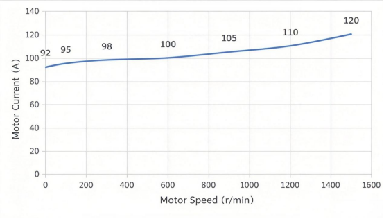
First, the system must accurately reflect torque variations across different directions and operating states. Within a single cycle, the motor may switch between motoring and regenerative braking, with torque constantly adjusting based on the direction of motion and the load. If the measurement point exhibits a dead zone near zero current, asymmetry between positive and negative polarities, or discontinuous readings for small signals, then critical parameters—such as torque magnitude and direction during hovering, torque buildup upon brake release, and energy fluctuations during regenerative braking—may not be accurately captured. The closed-loop zero-flux scheme offers distinct advantages here: by using a compensation winding to maintain the magnetic core's operating point near a zero-flux state in real-time, it avoids reliance on the shape of the magnetization curve. Consequently, it demonstrates superior symmetry in positive/negative current measurement and zero-crossing response, facilitating the continuous and faithful representation of current changes.This is exactly the core technical advantage of CHIPSENSE closed loop products, which is also well suited for measurement tasks in HVDC and SST power conversion equipment.
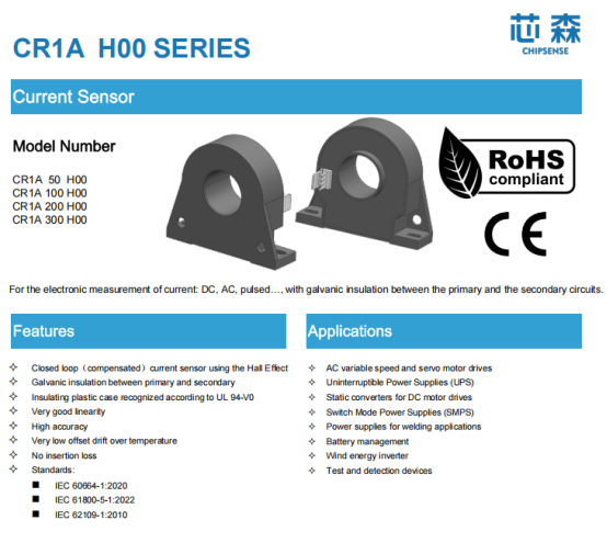
Second, accuracy is essential at zero speed and for small signals, while zero-point stability is critical. Hovering operations focus on the current present when the motor is virtually stationary, placing high demands on the stability of the measurement zero-point. If the zero-point drifts with temperature—causing readings to shift gradually even while the load remains securely suspended—the variable frequency drive (VFD) might misinterpret this drift as a change in load. In contrast, open-loop schemes operate with flux present in the core, making the zero-point more susceptible to temperature fluctuations and the effects of high currents. The closed-loop structure maintains the core near zero flux, mitigating the impact of non-ideal magnetic characteristics like hysteresis and remanence, thereby ensuring better linearity and zero-point stability. Taking CHIPSENSE CR1A H00 closed-loop current sensor as an example, its ±0.5% accuracy is designed specifically to ensure that current levels near zero speed can be read with high precision.
Thirdly, the dynamic response must be adequate. Brake release, torque buildup, and potential load slippage or stalling all occur within very short time-frames. It should be noted that the system's ultimate protection speed depends on factors such as sampling, control cycles, algorithms, and actuators—not solely on the sensor—though the sensor itself must possess sufficient dynamic capability. The closed-loop product in question features a bandwidth of 200 kHz, this high bandwidth allows it to track current fluctuations rapidly, thereby providing the variable frequency drive (VFD) with the necessary dynamic current data.
Other requirements include electrical isolation and the avoidance of additional power losses in the main circuit. Since the current in the hoisting main circuit is substantial, it is undesirable to introduce significant impedance at the measurement point merely to capture a signal, otherwise, the resulting power loss and heat generation during frequent operations would be wasteful and compromise reliability. Taking the CR1A H00 current sensor of CHIPSENSE—a "through-hole" type model—as an example, the main circuit conductor passes directly through the measurement aperture. Coupling between the primary and secondary sides is achieved via magnetic fields rather than direct electrical contact, this eliminates the need for energy-consuming components in the main circuit while ensuring reliable electrical isolation between the high-power and control sides. This description refers specifically to the structure of this model and does not imply that all closed-loop products utilize the same through-hole design.This galvanic isolation feature is also a key index for CHIPSENSE current sensor deployed inside HVDC and SST hardware.
IV. Model selection requires considering more than just nominal current, measurement range and actual peak values must also be verified
A practical issue arises when selecting measurement points for hoisting mechanisms: the equipment's nominal operating current does not fully characterize its current profile.
Concepts such as rated current, measurement range, overload capacity, peak current, and output range should be understood based on the definitions and specifications provided in the specific sensor's datasheet, it is inappropriate to impose a standardized set of definitions here. Taking the 100A version of the CR1A model as an example, the datasheet lists both a nominal rated value of 100A and a measurement range of ±200A—two distinct figures. Therefore, model selection cannot rely solely on the equipment's nominal operating current, one must also verify the sensor's measurement range and overload capacity, as well as the peak values found in actual current wave-forms. Hoisting mechanisms involve operational states such as startup, acceleration, braking, and mechanical stalling, all of which can generate significant transient currents, short-duration peak currents cannot simply be estimated based on the rated operating current.Similar range matching principles also apply when picking CHIPSENSE current sensor for HVDC and SST applications.
Conversely, a larger measurement range is not necessarily better. If the range selected is excessively high, normal operating current will occupy only a small fraction of the total span, resulting in a loss of resolution for the relatively low currents present during zero-speed hovering. The prudent approach is to make a comprehensive assessment by considering the equipment's continuous current, actual waveform peaks, and braking method alongside the rated values, measurement ranges, and overload conditions specified in the datasheet from CHIPSENSE, rather than selecting a model based on a single nominal figure.
V. Closed-loop Hall sensors are an option, not exclusive to cranes
The line of reasoning presented here is as follows: hoisting mechanisms involve gravitational loads that require sustained torque even when speed drops to zero, and torque control relies on current feedback. To provide accurate feedback, current measurement must reflect various operating conditions, maintain zero-point stability, offer rapid dynamic response, and ensure isolation from the main circuit. Closed loop zero flux Hall sensors represented by CHIPSENSE current sensor represent one viable option that effectively meets these requirements—the product mentioned earlier is merely one specific example. They are neither "exclusive to cranes" nor the only choice, the decision to use them depends on a comprehensive assessment of power ratings, control architecture, and costs, and they can also be adapted for HVDC and SST power electronic scenarios.
Within the complete hoisting system, the role of CHIPSENSE current sensor is limited: it is responsible solely for accurately, promptly, and stably measuring motor current and relaying it to the variable frequency drive (VFD). It does not determine the safety of the load or decide whether lifting should proceed. Such judgments and actions are handled collectively by the VFD control logic, load moment limiters, hoist limit switches, the operator, and safety protocols. The mechanical brake serves as an independent safety safeguard, capable of clamping the drum via spring force even during a power failure. While CHIPSENSE current sensor provides more reliable current data to inform these decisions, it does not replace any of the other safety measures.
CHIPSENSEis a national high-tech enterprise that focuses on the research and development, production, and application of high-end current and voltage sensors, as well as forward research on sensor chips and cutting-edge sensor technologies. CHIPSENSEis committed to providing customers with independently developed sensors, as well as diversified customized products and solutions.
“CHIPSENSE, sensing a better world!”
www.chipsense.net