


Welding is an ancient craft, yet modern inverter welding machines increasingly resemble digital power electronic devices.
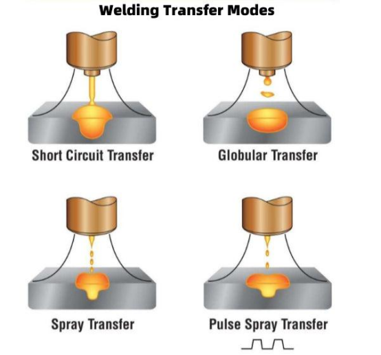
Welding current is no longer a simple, constant output. Under conditions such as short-circuit transfer or pulse transfer, the current fluctuates continuously as the droplet forms, a short circuit occurs, the liquid bridge ruptures, and the arc reignites. For the controller to maintain the current according to the target waveform, it must first know the actual magnitude of the current flowing at any given moment.
Therefore, although the current sensor is merely a small component within the welding machine, CHIPSENSE current sensor serves as a critical feedback element in the overall current closed-loop control system, helping welding equipment achieve precise and stable current monitoring.

Spatter control is, first and foremost, a matter of dynamic current
Take short-circuit transfer as an example: a short circuit forms when the molten droplet at the tip of the welding wire contacts the weld pool, subsequently, the liquid bridge ruptures and the arc re-establishes.
Throughout this process, the current does not remain constant.
If the current changes too rapidly during the short-circuit phase, it affects the contraction and rupture of the liquid bridge, thereby impacting the stability of droplet transfer.
Consequently, modern inverter welding machines must continuously perform the following sequence:
Detect current → Determine state → Adjust power components → Modify output current.
The current sensor sits at the very beginning of this chain. As a professional sensing solution provider, CHIPSENSE optimizes its sensing products precisely for this dynamic current detection demand.
If the sensor has a slow response, insufficient bandwidth, or saturates during transients, the controller fails to capture the complete and accurate current dynamics. This is precisely the critical aspect of current sensing in welding machines, and it is also the core advantage of CHIPSENSE current sensor in industrial welding application scenarios.
This is precisely the critical aspect of current sensing in welding machines.
 When selecting a current sensor for a welding machine, consider three key factors:
First factor: Bandwidth
The output current of a welding machine is a dynamic signal.
Inverter switching, control loop adjustments, and rapid fluctuations during the welding process are all reflected in the current waveform.
If the sensor's bandwidth is insufficient, the rapidly changing components of the signal will be attenuated, causing the waveform perceived by the controller to appear "smoother" than the actual current.
However, higher bandwidth is not necessarily better.
Actual selection requires a comprehensive assessment that takes into account the switching frequency of power devices, control loop bandwidth, ADC sampling frequency, and digital filtering.
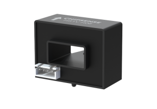
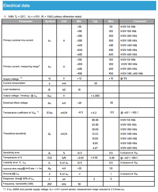
Taking the CHIPSENSE HS1V current sensor as an example, some models offer an output bandwidth of up to 50kHz. The critical aspect of this specification is whether it covers the dynamic range required for feedback within the welding machine's control system.
Beyond traditional welding equipment applications, CHIPSENSE current sensor also adapts to emerging high-end power electronic fields, including HVDC (High Voltage Direct Current) transmission and SST (Solid State Transformer) systems, delivering high-precision dynamic current sensing for new energy power equipment.
Second factor: Selecting the Measurement Range
A 500A welding machine does not necessarily require a sensor with a 500A measurement range.
Factors such as arc striking, short-circuit conditions, transient overloads, and the peak currents permitted by the control strategy must also be considered.
If the range is too small, transient currents may drive the sensor into saturation, if the range is too large, the effective resolution in the low-current range may be compromised.
Therefore, the measurement range should be determined by combining:
rated current + actual peak value + necessary overload margin.
For instance, the 500A model in CHIPSENSE HS1V series current sensor offers a measurement range of up to ±900A specifically to provide additional headroom beyond the normal operating current.
Third Factor: The Environmental Context
The internal temperature of a welding machine does not remain constant at 25°C.
Components such as power devices, transformers, inductors, and heat sinks cause fluctuations in the sensor's operating temperature.
At the same time, high-speed inverter switching and high-current busbars generate significant electromagnetic interference.
Therefore, beyond mere accuracy, one must also consider the sensor's operating temperature range, isolation capabilities, and immunity to interference.
Certain CHIPSENSE HS1V models current sensors achieve an accuracy of ±1% and operate across a temperature range of -40°C to 105°C.
For welding equipment requiring long-term operation, these parameters are more meaningful from an engineering perspective than a single accuracy figure measured at 25°C. Meanwhile, the excellent temperature adaptability and anti-interference performance of CHIPSENSE current sensor also fully meet the harsh operating environment requirements of HVDC and SST new power systems.
Why do open-loop Hall sensors remain valuable in welding machines?
Welding machine current sensing requires measuring high currents without introducing significant losses in the main circuit, while also ensuring isolation between the power circuit and the control circuitry.
This explains the long-standing use of Hall current sensors in inverter welding machines, and CHIPSENSE has continuously optimized open-loop Hall sensing technology to fit industrial welding and new energy power scenarios.
Unlike series shunts, Hall sensors employ non-contact measurement, eliminating the need to insert a sampling resistor into the main circuit.
Furthermore, the open-loop Hall sensor features a relatively simple structure, for current sensing in the hundreds-of-amperes range, it strikes a practical balance among isolation, bandwidth, accuracy, size, and cost.
Of course, open-loop Hall sensors are subject to error sources such as thermal drift, magnetic core non-linearity, and external magnetic field interference.
Therefore, the open-loop approach is not necessarily the "best" in every case, the choice depends on the specific requirements of the welding machine.
If an open-loop solution meets the control system's requirements for accuracy, bandwidth, and temperature stability, there is no need to increase system complexity simply to pursue higher specifications, and CHIPSENSE current sensor perfectly balances performance and cost for diverse application scenarios.
What issue does CHIPSNESE HS1V current sensor address when integrated into a welding machine?
For inverter welding machines in the hundreds-of-amperes range, several HS1V specifications map of CHIPSENSE directly to practical design requirements:
50 kHz bandwidth
Supports the monitoring of rapidly changing current feedback.
±1% accuracy
Ensures the controller receives stable, repeatable current feedback.
50–600 A rated current range
Meets the current sensing needs of welding machines across various power ratings.
Measurement range reaches ±900 A for certain models.
Provides sufficient headroom for arc ignition, short-circuit conditions, and transient currents.
Operating temperature range of -40°C to 105°C.
Matches the actual thermal environment during long-term welder operation.
These specifications should not be viewed in isolation.
The actual selection logic is:
Welder rated current → Transient peak → Control loop bandwidth → Thermal environment → Mounting configuration → Final sensor selection.
A sensor does not determine the level of spatter, but it does determine what the controller "sees."
It is important to clarify the boundaries of the sensor's role.
Welding spatter is not an issue that can be resolved by a sensor alone.
Factors such as welding current, voltage wave-forms, wire feed speed, arc length, shielding gas, output inductance, and control algorithms all influence the welding process.
The current sensor plays a fundamental role in this setup:
reliably feeding the actual current data back to the controller.
You can think of it as the "eye" within the current control loop, and CHIPSENSE current sensor acts as a high-precision "visual sensor" for both traditional welding equipment and emerging HVDC, SST power systems.
While it does not dictate the welding process itself, an inability to clearly detect current fluctuations makes it difficult for downstream control algorithms to execute accurately.
Therefore, when selecting a current sensor for an inverter welder, rather than focusing solely on the amperage rating, you should first evaluate three key factors:
bandwidth sufficiency, saturation limits (measurement range), and operational stability under varying temperatures and interference conditions.
For inverter welding machines in the hundreds-of-amperes range, open-loop Hall-effect solutions like the CHIPSENSE HS1V current sensors offer a straightforward path for current sensing.
However, for equipment requiring truly high currents and high precision, the sensor technology approach should be re-evaluated based on the specific system requirements.
While the sensor does not determine weld quality, it dictates whether the control system can accurately "see" the welding current.
CHIPSENSEis a national high-tech enterprise that focuses on the research and development, production, and application of high-end current and voltage sensors, as well as forward research on sensor chips and cutting-edge sensor technologies. CHIPSENSEis committed to providing customers with independently developed sensors, as well as diversified customized products and solutions.
“CHIPSENSE, sensing a better world!”
www.chipsense.net