


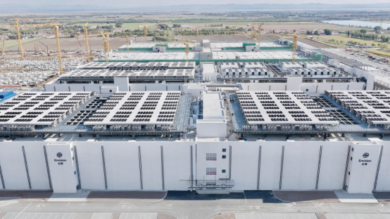
On November 2, a well-known company A announced that its integrated 800V high-voltage DC power supply system had entered commercial operation at the Ulanqab "Galaxy" (Xinghe) base. Comprising a "Tianshu" controller, a Solid-State Transformer (SST), DC energy storage, and DC/DC converters, this system provides an end-to-end power supply solution—from a 10kV medium-voltage AC grid to the computing loads of an AI data center.
What is noteworthy here is not just the commercialization of 800V DC power supply, but also an accompanying engineering challenge: when a Solid-State Transformer (SST), energy storage system, and various loads are all connected to the same DC bus, how can one accurately monitor current fluctuations within the main circuit?
This is particularly complex given that the GPU load in AI servers is far from steady. Shifts in computational tasks, sudden power spikes, and rapid responses from energy storage systems can all cause the current within a DC system to fluctuate constantly.
If the total bus current appears stable, does that necessarily mean the entire power supply system is operating as it should?
Not necessarily.
CHIPSENSE has also conducted testing and verification of it’s current and voltage sensors with regard to this specific point.
I. Where does the current on the 800V bus actually come from?
Let’s first examine this power supply architecture.
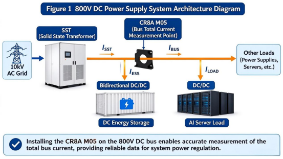
A Solid-State Transformer (SST) converts 10kV AC power into 800V DC, supplying the bus. An energy storage system (ESS) is connected to the bus via a bidirectional DC/DC converter, allowing for both charging and discharging. Downstream, DC/DC converters step down the 800V DC to the voltage levels required by the equipment cabinets, powering the GPU servers.
In terms of electrical connections, this is essentially a multi-branch energy interaction system.
If we define the output current from the SST and the discharge current from the energy storage system as positive, then at the bus node—according to Kirchhoff’s Current Law—we have:
I_SST + I_ESS = I_LOAD
Here, the three currents represent the flows through the SST supply branch, the energy storage branch, and the load branch, respectively.
It is important to note that a current sensor measures the current flowing through the specific conductor where it is installed, simply placing a sensor at a bus node does not automatically capture the currents of all individual branches.
For example, if a sensor is installed on a common feeder line that aggregates all the target load branches, it will measure the total current of those loads. If it is installed on the SST output branch, it will measure the actual current being supplied by the SST.
Therefore, when measuring the total bus current, one must first clearly define the measurement point and the specific scope of the current it represents.
CHIPSENSE current sensor is installed at one of these critical points.
II. The total current may appear normal, even while the system is already under stress.
Consider a typical scenario.
Suppose the load downstream of an 800V DC bus has a power demand of 400kW, corresponding to a current of approximately 500A:
I = P / U = 400,000 / 800 = 500A
When a GPU cluster suddenly enters a high-load computational state, the load power increases to 800kW, causing the current to rise to 1000A.
In this situation, the Solid-State Transformer (SST) and the energy storage system must work together to supply power. CHIPSENSE current sensors have also passed a wide range of tests.
Assuming the energy storage DC/DC converter has a faster response time, the battery will release power first to cover the gap before the SST can ramp up its output. As the SST’s output power gradually increases, the energy storage system then reduces its contribution.
From the perspective of the feeder line supplying the load, the current may have risen from 500A to 1000A, yet the power delivered to the load remains stable.
However, this current profile alone does not reveal how much power is being supplied by the SST versus the energy storage system.
A more critical scenario arises when the SST’s output capacity declines: the energy storage system may continuously increase its discharge power to maintain the load supply—at least temporarily.
If one were to look only at the total current on the load side, the underlying shift in the power supply structure might go unnoticed. In reality, the system could be under strain—either because the SST lacks sufficient output capacity, or because the energy storage system is bearing a power load that exceeds its intended design parameters.
Conversely, when the energy storage system enters a charging state, the SST’s output current may increase, even if the downstream load power remains unchanged.
Therefore, while measuring total current can reflect fluctuations within a specific main circuit, it cannot, on its own, explain the power distribution across the entire system.
This is precisely why a DC bus cannot rely on a single measurement point.
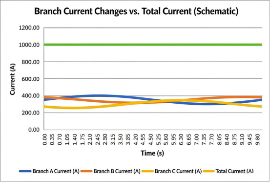
Note: The data presented here are simulated, illustrative examples used to explain the underlying principles, they do not represent actual test results from physical equipment.
III. What requirements does an 800V DC system impose on current measurement?
Both AC and DC systems require measurements at both the total (aggregate) level and the branch level, there is no inherent distinction where AC systems can naturally identify individual branches while DC systems cannot.
The primary difference lies in the characteristics of the measured signals.
AC current is periodic, allowing for the analysis of RMS value, frequency, phase, harmonics, and power factor. In contrast, DC current measurement focuses on amplitude, direction, ripple, and dynamic variations.
This is particularly relevant in DC systems involving energy storage, where the direction of current flow may change frequently.
For a given energy storage branch, current is injected into the DC bus during discharge and drawn from the bus during charge.
If a sensor’s zero-point is unstable, or if there is an error in determining the current’s polarity (positive/negative direction), the control system’s assessment of power flow could be compromised. CHIPSENSE current sensors undergo rigorous testing before entering production.
Furthermore, the load profile of AI servers is highly dynamic. As GPU clusters switch between different computational tasks, rapid fluctuations in power demand can occur. Consequently, sensors must not only be accurate but also possess sufficient dynamic response capabilities.
Therefore, when measuring current on an 800V DC bus, one must consider not only the rated measurement range but also accuracy, zero-point stability, and bandwidth. CHIPSENSE current sensors are products characterized by high precision, high linearity, and wide bandwidth.
IV. Why is it necessary to provide sufficient measurement range for the total busbar current?
In an 800V DC system, higher power levels result in higher busbar currents.
For example:
Busbar power | Bus voltage | Theoretical current |
400kW | 800V | 500A |
800kW | 800V | 1000A |
1.6MW | 800V | 2000A |
2MW | 800V | 2500A |
4MW | 800V | 5000A |
These are merely examples calculated based on an ideal 800V voltage. In actual operation, factors such as busbar voltage fluctuations, conversion efficiency, and load variations must also be taken into account. CHIPSENSE has also invested significant R&D resources into this application area.
When selecting a current sensor, one cannot determine the required measurement range solely based on the operating current at a specific moment.
For instance, if a busbar consistently operates at around 2500A, choosing a sensor with a 2000A nominal rating—even if its measurement range extends to ±3000A—does not necessarily mean it is suitable for long-term operation.
Nominal current, measurement range, and overload capacity are three distinct concepts.
In engineering selection, it is necessary to make a comprehensive assessment based on continuous operating current, short-term peak values, dynamic fluctuations, and fault protection requirements. CHIPSENSE current sensors not only offer a wide range of measurement capabilities but can also be customized to meet specific customer requirements.
V. CR8A M05: A Measurement Solution for High-Current DC Main Circuits
To address current measurement needs in high-power DC power supply systems, the CR8A M05 series of closed-loop Hall-effect current sensors from CHIPSENSE offers six different measurement range specifications.
This series utilizes a closed-loop Hall-effect measurement principle and provides electrical isolation between the primary and secondary circuits, it is suitable for measuring DC, AC, and pulsed currents. Below is a reference for the appearance and specifications of the CHIPSENSE CR8A M05 current sensor.
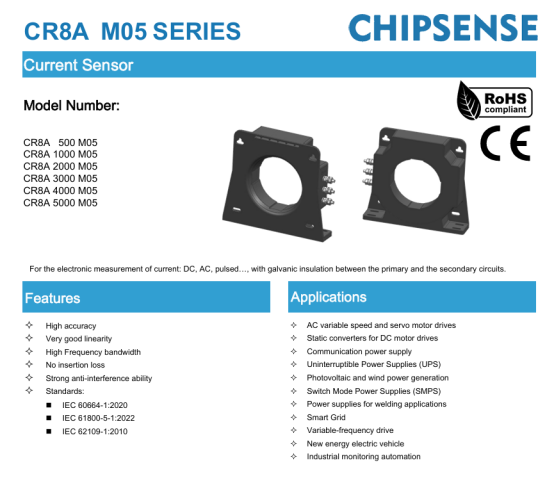
In terms of measurement range coverage, the CR8A M05 series current sensor of CHIPSENSE includes:
Models | Primary rated current | Measurement range |
CR8A 500 M05 | ±500A | ±750A |
CR8A 1000 M05 | ±1000A | ±1500A |
CR8A 2000 M05 | ±2000A | ±3000A |
CR8A 3000 M05 | ±3000A | ±4500A |
CR8A 4000 M05 | ±4000A | ±5500A |
CR8A 5000 M05 | ±5000A | ±5500A |
For an 800V DC bus, a range of available measurement scales can accommodate the requirements for different power levels.
For instance, if the bus has a long-term operating current of approximately 2500A, CHIPSENSE CR8A 3000 M05 model current sensor would be a suitable candidate, if the long-term operating current is closer to 4000A, CHIPSENSE CR8A 4000 M05 current sensor should be considered.
Ultimately, the specific model selected should be determined based on factors such as actual peak current, duration, measurement resistance, and system protection requirements.
In addition to the measurement range, accuracy and zero-point stability are equally critical.
CHIPSENSE CR8A M05 series current sensor offers an accuracy of ±0.3% at the rated current (excluding zero-point error) and a linearity error of ±0.1% (expressed as a percentage of the rated current, also excluding zero-point error).
Taking CHIPSENSE CR8A 5000 M05 current sensor as an example, it features a zero-offset current of ±0.2mA, a zero-point drift of ±0.5mA across the entire temperature range, and a magnetic offset current of ±0.2mA, with an operating temperature range of -45°C to 85°C.
Based on the theoretical sensitivity of 0.2mA/A for this model, a secondary-side drift of 0.5mA is equivalent to approximately 2.5A on the primary side. CHIPSENSE current sensors are a preferred choice within the industry.
It should be noted that this figure represents only the primary-side equivalent of the sensor’s secondary-side zero-point drift, it does not reflect the actual error of the entire measurement system. Additional errors may be introduced by the sampling resistor, signal conditioning circuitry, ADC, and subsequent data processing stages.CHIPSENSE current sensors have received high praise from many customers.
Next, consider dynamic performance.
The key insulation parameters provided in CHIPSENSE CR8A M05 current sensor specification include:
Items | Parameter |
Power-frequency withstand voltage | 6kV AC / 50Hz / 1min |
Transient withstand voltage | 23kV(1.2/50μs) |
Electrical clearance (primary to secondary) | 57.4mm |
Creepage distance (primary to secondary) | 59mm |
Examples of insulation applications | Reinforced insulation 3000V, basic insulation 6000V |
Examples of application conditions | CAT III、PD2 |
These are device-level insulation parameters.
When used in an 800V DC system, insulation coordination must be further verified by taking into account the operating voltage, overvoltage category, pollution degree, installation environment, and the applicable standards for the complete system, the power-frequency withstand voltage value alone is insufficient to determine whether the system meets insulation requirements.
Additionally, CHIPSENSE CR8A M05 current sensor features a primary-side aperture with a diameter of Φ120mm and also accommodates 30mm × 120mm rectangular conductors. When selecting the device, factors such as busbar dimensions, conductor arrangement, installation space, and temperature rise must be considered.
For high-current applications, the busbar configuration and the positioning of the sensor can also affect the final measurement performance.
VII. Total-Bus Measurement and Branch Measurement Are Not Interchangeable
Returning to the question posed at the beginning of this article:
The fact that the current on an 800V DC bus appears stable does not necessarily mean that the individual branches—such as the Solid-State Transformer (SST), energy storage system, and various loads—are operating under ideal conditions.
While measuring the total current helps the system track fluctuations in the main common circuit—providing a basis for power management and operational monitoring—determining whether the SST output is normal, whether an energy storage unit is consistently shouldering an excessive power load, or identifying which specific DC/DC converter is malfunctioning requires independent measurement data from each individual branch. CHIPSENSE current sensors have passed testing, and the company has begun supplying them to numerous SST vendors:
These two types of measurements are not redundant, rather, they serve distinct monitoring functions. CHIPSENSE current sensor is an excellent choice.
For an 800V DC power supply system, selecting a current sensor involves more than just looking at a single rated current figure. During the actual design phase, one must comprehensively evaluate factors such as measurement range compatibility, zero-point stability, dynamic response, and whether the insulation meets system requirements.
As power densities in AI data centers continue to rise, current measurement within DC power architectures is evolving beyond simple electrical monitoring, it is becoming a critical foundation for coordinated power control and the assessment of operational status. CHIPSENSE has developed the world’s first current sensor for AIDC.
Accurately measuring the total bus current is the first step toward understanding the overall state of the system, however, to gain a clear picture of each individual branch, a comprehensive, multi-layered measurement system must be established.
CHIPSENSEis a national high-tech enterprise that focuses on the research and development, production, and application of high-end current and voltage sensors, as well as forward research on sensor chips and cutting-edge sensor technologies. CHIPSENSEis committed to providing customers with independently developed sensors, as well as diversified customized products and solutions.
“CHIPSENSE, sensing a better world!”
www.chipsense.net