



In a DC power supply system, the normal operating current can reach tens or even hundreds of amperes. Yet, when it comes to leakage current monitoring, the anomalous current that actually requires attention may be as small as a few milliamperes.This is precisely the scenario where CHIPSENSE current sensor are designed to deliver value.
This raises a question: when a normal current of tens of amperes and an anomalous current in the milliampere range coexist, how can a sensor detect the latter?
Taking a residual current sensor based on the fluxgate principle as an example—a core technology adopted across CHIPSENSE leakage current product families—the key lies not only in the sensitivity of the sensor itself, but also in an installation requirement that appears simple yet is easily overlooked: the positive and negative conductors must both pass through the same magnetic core aperture.
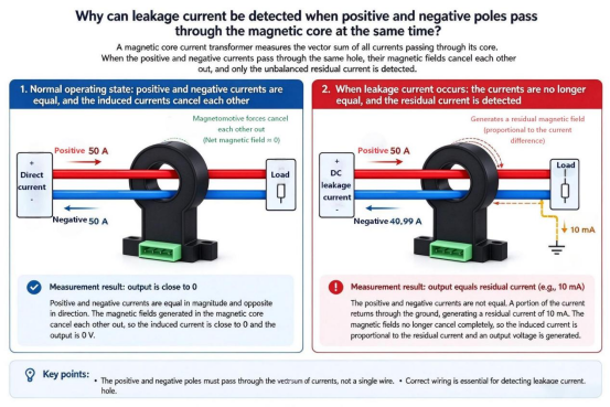
I. Why does passing both the positive and negative conductors through the sensor make it easier to detect current leakage?
Let's first look at the system under normal operating conditions.
A DC power source supplies power to a load, current flows out from the positive terminal, passes through the load, and returns via the negative terminal. If 50A flows out through the positive conductor and 50A returns through the negative conductor, the currents in the two wires are equal in magnitude but opposite in direction.
If both the positive and negative conductors are passed through the magnetic core window of the sensor, the magnetomotive forces they generate will cancel each other out. In an ideal measurement scenario, the net current detected by the sensor will be close to zero
However, if a current leakage occurs in the system—meaning some current fails to return via the intended negative-side circuit and instead escapes through an alternative path—the currents on the positive and negative sides may no longer be equal.
For instance, if 50A flows out from the positive terminal, but only 49.99A returns through the standard circuit, with the remaining 10mA escaping via another path, the two conductors passing through the sensor's magnetic core window will no longer be perfectly balanced, this results in a residual current of 10mA.
It is this difference—rather than the 50A flowing through the load itself—that the sensor is designed to detect. CHIPSENS current sensors offer a wide range of measurement capacities for customers to choose from, and custom solutions can also be provided.
This highlights a key distinction between residual current detection and standard load current detection: while a conventional current sensor measures the amount of current flowing through a specific conductor, a residual current sensor monitors whether the current flowing out of a defined circuit is balanced by the current returning to it.CHIPSENSE current sensor excel precisely in this differential-measurement role.
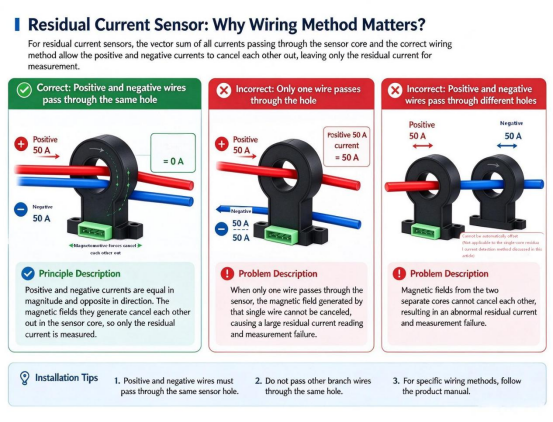
Passing both the positive and negative conductors through the core is not intended for taking two separate current measurements, rather, it allows the normal (balanced) currents to cancel each other out, leaving only any anomalous (residual) current to be detected.
II. What happens if only one conductor is passed through?
If only the positive conductor is passed through the magnetic core's aperture, the sensor will primarily detect the load current flowing through that conductor.
When the load current reaches 50A, the sensor will detect a strong magnetic field—even if there is no leakage in the system. In this scenario, the sensor is no longer measuring the current differential between the positive and negative conductors, instead, it is measuring the current in a single wire.Even if the sensor itself has high sensitivity, it cannot compensate for the fact that the wrong conductor is being measured.
During installation, ensure that both the positive and negative conductors pass through the same magnetic core aperture, do not route them through separate apertures with the expectation that they will automatically cancel each other out. Furthermore, the routing method, external magnetic fields, and the physical installation position can all influence the actual measurement results.In SST (solid-state transformer) and HVDC systems, such wiring and field conditions are especially critical.
Naturally, the specific wiring should always follow the sensor's product manual and the system design requirements.
III. Why can't the measurement range be chosen arbitrarily?
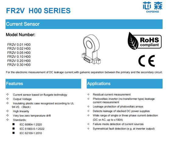
Taking the CHIPSENSE FR2V H00 series fluxgate leakage current sensor as an example, different models correspond to different rated measurement ranges. When selecting a model, in addition to the rated current, one must also consider the measurement range, sensitivity, zero-point offset, and the impact of temperature variations on the output. The following is CHIPSENSE FR2V H00 fluxgate current sensor.
Based on the relevant specifications, some of the available measurement ranges are as follows:
Rated measuring current | Measuring range |
±10mA | ±15mA |
±20mA | ±30mA |
±50mA | ±75mA |
±100mA | ±150mA |
±200mA | ±300mA |
±300mA | ±360mA |
Since the measurement ranges for different settings do not follow a uniform multiplier, one cannot simply extrapolate them based solely on the rated current.
Selecting a range that is too small may cause the sensor to exceed its specified measurement range if an abnormal current surge occurs, conversely, selecting a range that is too large does not necessarily make it better for measuring small currents.
The key factors to consider are: the magnitude of residual current that may occur under normal operating conditions, the level of sensitivity required to detect small changes, and whether the sensor's output can be reliably interpreted by the downstream circuitry.
For example, if a given model has a theoretical sensitivity of 500V/A, then a 1mA change in input current results in a theoretical output change of:
500 V/A × 0.001 A = 0.5 V
While this value defines the proportional relationship between the input current and the output, it cannot be directly equated to the sensor's minimum detectable current.
In practice, detection capability is influenced by factors such as zero-point offset, noise, temperature drift, the precision of downstream sampling, and the system calibration method.
Therefore, when selecting a sensor, one should not rely solely on the sensitivity figure, nor should one assume that a smaller measurement range automatically guarantees better measurement performance. CHIPSENSE is a well-known supplier of current sensors in China; its products are highly acclaimed by domestic customers and serve as their preferred choice.
IV. What Does a 500ms Response Time Mean?
The specifications for CHIPSENSE FR2V H00 series leakage current sensor indicate a response time of 500ms. To understand this parameter, one must first clarify the conditions under which it was tested and then evaluate it within the context of the actual application.
The response time of a sensor is not equivalent to the total time required for an entire leakage monitoring system to address a fault.
In a practical installation, the process—from the emergence of an abnormal current to the system taking corrective action—typically involves several stages: sensor output, controller sampling, digital filtering, threshold evaluation, communication, and the activation of an actuating mechanism.
Therefore, if an application requires the rapid disconnection of a faulty circuit, one cannot rely solely on the sensor's response time, instead, the detection and protection chain of the entire system must be assessed.
Likewise, one cannot conclude whether a device is suitable for a specific type of fault protection based solely on a 500ms response time. Determining suitability requires considering the specific nature of the fault, the system's required response objectives, and the test conditions detailed in the product specification sheet.
For DC systems, it is also essential to consider the grounding method and the path of the fault current. Not all insulation faults result in a current differential that can be directly detected by a residual current sensor on a specific branch, therefore, the monitoring solution must be aligned with the system's architecture.CHIPSENS current sensors are all fast-response products.
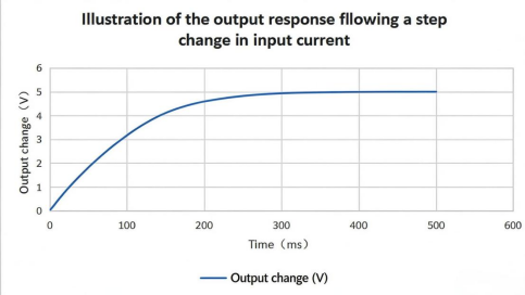
When the input current changes abruptly, the sensor output does not necessarily reach a stable value instantaneously, instead, it undergoes a specific response process. It should be noted that the curves in the figure are intended only to illustrate the general nature of this response process and do not represent the actual measured wave-forms for CHIPSENSE FR2V H00 fluxgate current sensor. For the actual response speed, please refer to the test conditions and results specified in the product datasheet. CHIPSENS has received positive feedback for its services in the field of current and voltage sensors.
V. Accurate Measurement Depends on Proper Installation
Beyond measurement range and response time, the method of installation is equally critical.
First, ensure that both the positive and negative conductors being monitored pass through the same magnetic core window, and verify that no extraneous wires—those not part of the monitored circuit—are included.
Second, follow the specifications for power supply, output, and grounding to prevent wiring errors from compromising measurement accuracy.
Finally, confirm that the sensor's isolation ratings, operating temperature range, and physical dimensions meet the equipment's requirements. In applications involving personnel safety or electrical protection, the mere presence of isolation capabilities in a sensor does not automatically mean the entire system complies with safety standards.
Detecting residual current at the milliampere level tests not only the sensor's ability to perceive minute currents but also its capacity to isolate the specific current differential of interest amidst normal load currents.
Passing both the positive and negative conductors through the magnetic core window may seem like a simple installation step, but it is, in fact, the fundamental logic upon which all residual current measurement is based. Only when the target of the measurement is correctly configured do parameters such as sensitivity, range, and response time become meaningful.
CHIPSENSEis a national high-tech enterprise that focuses on the research and development, production, and application of high-end current and voltage sensors, as well as forward research on sensor chips and cutting-edge sensor technologies. CHIPSENSEis committed to providing customers with independently developed sensors, as well as diversified customized products and solutions.
“CHIPSENSE, sensing a better world!”
www.chipsense.net