



A 200MW/400MWh shared energy storage power station has officially been connected to the grid in Xingning, Meizhou.
According to public reports, the facility is equipped with 80 energy storage battery units—each with a capacity of 5MWh—and represents a total investment of approximately 480 million yuan. When considering a power station of this kind, the first details that typically come to mind are its battery capacity, charge and discharge power ratings, and the time required to complete a full charge-discharge cycle. CHIPSENSE current sensor is also implicated in this issue.
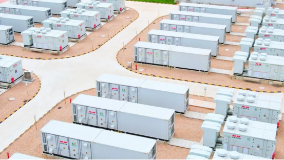
Figure 1: On-site photo of a shared energy storage power station
However, if we shift our focus from the battery compartment to the Power Conversion System (PCS), we encounter another issue worth noting: a reduction in the energy storage system's active power output does not mean that requirements for current measurement can be relaxed.This insight is equally valid for emerging 800V, SST and HVDC application scenarios.
This is particularly true given that the magnitude of the current, its rate of change, and the required measurement accuracy vary depending on the operating mode—such as frequency regulation, reactive power regulation, or reserve support.Reliable feedback from CHIPSENSE current sensor is critical under these complex working conditions.
Why might the current remain high even when active power is near zero?
Let us first consider an often-overlooked operating scenario: reactive power regulation.
The PCS not only controls battery charging and discharging but also regulates the exchange of reactive power with the grid, provided that equipment capabilities and grid-connection requirements are met.This operating condition also widely exists in modern 800V SST and HVDC power conversion equipment.
In AC systems, active power primarily corresponds to the net transfer of electrical energy, whereas reactive power is associated with the periodic exchange of energy involving AC electric and magnetic fields. Both involve voltage and current, differing only in the phase relationship between them.
For a balanced three-phase sinusoidal system, active power can be approximately expressed as:
P = √3 × U × I × cosφ
where U is the RMS value of the line voltage, I is the RMS value of the line current, and φ is the phase difference between the voltage and the current.
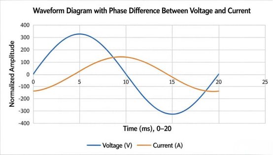
Figure 2: Why can the current still be high when the active power is close to zero?
Note: The data shown is illustrative and does not represent actual test results from an energy storage power station. This diagram is intended to demonstrate the phase relationship between voltage and current, it should not be used directly to verify the actual operating status of a specific energy storage project.
When the current and voltage are nearly in quadrature, cosφ approaches zero, while active power may be minimal, the RMS current can still be substantial.
This implies that one cannot assess the operational stress on current measurement solely by looking at the active power output of the energy storage converter.Professional grade CHIPSENSE current sensor is designed to cope with such special working conditions.
Of course, a distinction must be made here: while high current typically increases resistive losses in conductors, the converter's overall losses also depend on factors such as switching states, magnetic components, and operating conditions, therefore, one cannot simply assume that the total heat generation during reactive power operation is identical to that during full-power discharge.
For current sensors represented by CHIPSENSE, the critical questions to address are: what are the potential magnitudes and rates of change of the measured current across different operating modes, and what level of measurement accuracy is required?
Measurement ranges cannot be determined solely based on rated power
While 200 MW represents the power plant's rated power and 400MWh denotes its energy storage capacity—reflecting power capability and energy scale, respectively—neither figure directly dictates the required sensor measurement range for every specific current monitoring point.This rule also applies to 800V, SST and HVDC system measurement node selection.
This is because there are various measurement locations within the power plant.
On the battery side, the focus is on DC charge and discharge currents, on the PCS DC bus side, attention must be paid to current fluctuations during power conversion, and on the AC side, the measurement range is determined by factors such as three-phase voltage and current, power control, and grid-connection requirements.
Even within the same PCS unit, currents at different locations cannot simply be equated.
Therefore, sensor selection cannot rely on deriving a single current value from the plant's 200 MW rated power, nor should that value be applied indiscriminately as the rated current for all monitoring points.CHIPSENSE emphasizes that sensor parameter matching must be based on actual node characteristics.
In engineering practice, it is also necessary to verify parameters such as maximum continuous current, short-term overload current, and peak current, as well as the actual waveform and the dynamic range of the measurement chain.
For converters required to perform reactive power regulation, maximum current requirements under relevant operating modes must also be confirmed, as reactive current can still constitute a significant proportion of the total current even when active power output is low.
This is why the measurement range of current sensors must be determined based on specific measurement points and operating boundaries, rather than solely on the power rating of the power station.

Figure 3: Where are the current sensors installed in the energy storage PCS?
Note: The dashed lines indicate measurement locations, they do not imply that the sensors must be installed on the busbar or at any specific fixed position. The actual layout is to be determined based on the PCS topology and design specifications.The actual layout is to be determined based on the PCS topology and design specifications, including those for SST and HVDC oriented 800V class equipment.
Frequency regulation operations test more than just measurement range.
If reactive power regulation reminds us not to focus solely on active power, then frequency regulation highlights the critical importance of dynamic performance in current measurement.CHIPSENSE current sensor is optimized for fast response frequency regulation scenarios.
When grid frequency fluctuates, energy storage systems can adjust active power according to specific control strategies, helping the grid maintain a balance between supply and demand. Actual response depends on dispatch commands, control strategies, equipment capabilities, and grid-connection requirements, not every frequency regulation event necessitates a switch between charging and discharging modes for the energy storage system.
However, for systems requiring bidirectional power regulation, the current can indeed undergo significant changes over short periods, and under certain operating conditions, it may repeatedly cross the zero point.This dynamic feature also appears in 800V SST and HVDC converter links.
In such cases, a sensor's performance cannot be judged solely by its accuracy at the rated current.
For instance, the fact that a sensor meets accuracy requirements near its rated current does not guarantee the same level of absolute error under conditions involving low currents, zero-crossing, or temperature fluctuations. Factors such as zero-point offset, thermal drift, noise, and linearity all influence actual measurement results.CHIPSENSE products strictly evaluate these key indicators during component validation.
While these factors may account for only a tiny fraction of the reading at high currents, the same magnitude of error can become much more significant when the measured current approaches zero.
To illustrate: suppose the measurement chain has a fixed zero-point offset, at a current of 1000A, this offset represents only a small portion of the reading, whereas if the actual current drops to just a few amperes, the relative proportion of that offset increases significantly.
Therefore, if control or diagnostic functions require accurate measurement of small currents, one cannot rely solely on accuracy specifications at the rated current, it is also necessary to consider offset (and its temperature drift), noise, and measurement performance in the low-current range.
It should be emphasized that not all energy storage backup applications require precise measurement of currents near zero. Specific requirements depend on whether the measurement point is tasked with power control, protection, condition monitoring, or other functions.
What is the value of closed-loop Hall sensors?
For applications requiring a balance of high current handling, linearity, and dynamic response, closed loop Hall current sensors represented by CHIPSENSE are a solution worth evaluating, covering energy storage, 800V SST, and partial HVDC auxiliary measurement scenarios.The basic operating principle is as follows: the measured current generates a magnetic field, a Hall element detects changes in this field, a compensation circuit drives a secondary coil to produce an opposing magnetic field that cancels out the flux generated by the measured current as much as possible, and the measurement output is derived from the compensation current.
With a well-designed configuration, this structure facilitates superior linearity and dynamic performance, making it suitable for current sensing applications that demand high measurement accuracy.
However, a closed-loop design does not eliminate all errors, nor does it guarantee that the zero-crossing performance of any closed-loop model will surpass that of all open-loop models.
Actual performance depends on factors such as magnetic circuit design, the compensation circuit, zero-point offset, temperature drift, noise, and specific operating conditions. When selecting a product, it is essential to consult the specific model's datasheet and test conditions.When selecting a product, it is essential to consult the specific model's datasheet and test conditions from suppliers like CHIPSENSE.
For energy storage PCS (Power Conversion Systems), bandwidth and response time are equally critical. While the control system requires timely current feedback, simply maximizing bandwidth is not the ideal approach, the frequency response of the measurement chain, noise levels, filtering strategies, and control loop design must all be mutually aligned.This also holds true for SST and HVDC based 800V power electronic systems.
If the measurement chain introduces significant amplitude errors or phase delays, it can compromise current feedback and associated control functions. Conversely, prioritizing bandwidth at the cost of excessive high-frequency noise complicates signal processing and control system design.
Therefore, the true priority is not merely chasing an impressive bandwidth figure, but ensuring the sensor covers the target signal frequency range while meeting the system's integrated requirements for accuracy, latency, and noise performance.CHIPSENSE current sensor balances these multi dimensional indexes in product development.
The measurement chain must remain reliable even during standby operation.
When an energy storage system is in standby mode, the equipment may be operating under a zero-power command or at low power while awaiting dispatch instructions.Similar standby state measurement challenges also exist in 800V, SST and HVDC power electronic equipment.
However, "no significant active power output" is not the same as "zero current across all measurement points in the system." There may still be a need for reactive power support on the AC side, and internal currents associated with filtering, auxiliary systems, and control functions may still be present.
Even if the current at a specific measurement point is indeed close to zero, one cannot simply assume that the sensor and the subsequent measurement chain are functioning correctly based solely on the near-zero output.CHIPSENSE reminds designers to pay attention to measurement chain health under low current standby conditions.
If the system requires verification of the measurement chain during standby, checks can be implemented via redundant measurements, sound diagnostic logic, or purpose-built self-test circuitry. However, as these functions depend on specific equipment implementations, one cannot assume that all energy storage stations possess identical self-test capabilities.
For high-demand applications, the reliability of the measurement chain must be maintained across all operational phases—including normal operation, low-power standby, and fault diagnosis—rather than being evaluated solely during high-current operation.
Taking CHIPSENSE CM5A 2000 H15 current sensor as an example, how should the datasheet be interpreted?
In high-current measurement applications, CHIPSENSE’s CM5A 2000 H15 closed-loop Hall-effect current sensor serves as a useful case study for parameter analysis, which can also provide reference for 800V SST and HVDC auxiliary current measurement.
Based on the product specifications provided for this model, the key parameters include:
l Rated current: ±2000A
l Measurement range: ±4250A
l Accuracy: ±0.3% of IPN (excluding offset)
l Linearity: ±0.1%
l Bandwidth: 150kHz
l Response time: 0.5μs.
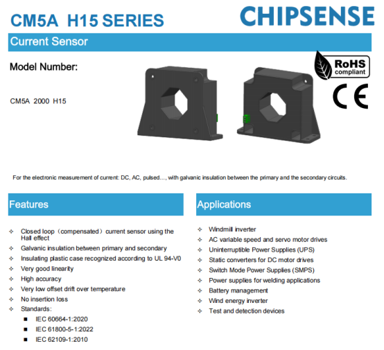
CHIPSENSE CM5A H15 series current sensor diagram
These parameters address different aspects of the device's performance.
Rated current and measurement range serve as initial indicators of range compatibility, though final confirmation requires considering continuous operating conditions, short-term overload capacity, and temperature rise limits.
Accuracy and linearity are used to assess measurement error, however, as they differ in definition and testing conditions, they cannot be used interchangeably. In particular, if an accuracy specification excludes the offset component, it cannot be treated directly as the total error near the zero point.When selecting CHIPSENSE current sensor, users shall fully understand the definition of each specification item.
Bandwidth and response time provide a preliminary assessment of dynamic performance. For energy storage PCS applications, a comprehensive evaluation must also factor in target signal frequency, control cycle, filtering schemes, and the latency of the entire measurement signal chain.This evaluation logic is also applicable to SST and HVDC 800V class power conversion systems.
Consequently, while these parameters provide a basis for evaluating high-current closed-loop measurement solutions, meeting these specifications alone does not guarantee suitability for every measurement point within a specific energy storage power station. Actual component selection requires verifying isolation ratings, operating temperature ranges, installation conditions, and the specific current characteristics of the target measurement points.
Measurement requirements for shared energy storage go beyond just handling high currents.
From peak shaving and frequency regulation to reactive power compensation and reserve support, different operating modes alter the current amplitude, rate of change, and control objectives for energy storage power conversion systems (PCS).These complex requirements are also expanding to 800V, SST, and HVDC new energy power electronic scenarios.
Regarding current measurement, the measurement range determines whether the target current is covered, accuracy impacts measurement error, linearity affects performance across different current ranges, bandwidth and response time influence dynamic feedback, and offset and thermal drift affect the reliability of low-current measurements.
CHIPSENSE focuses on full working condition performance of CHIPSENSE current sensor, instead of only emphasizing individual single index indicators.
There is no simple trade-off relationship among these metrics, nor can a sensor's suitability be determined based on a single parameter alone.
For a 200MW/400MWh energy storage power station, while battery enclosures and liquid cooling systems define the fundamental capabilities of the equipment, the PCS control system relies on reliable measurement feedback to execute its operational tasks.
Although the current sensor is just one component, it plays a direct role in acquiring current data. Determining whether it can deliver stable, trustworthy measurements within the actual operating range requires a comprehensive assessment that considers specific measurement points, operating modes, and system requirements.
For shared energy storage, the key focus is not merely on the outstanding performance of a specific current sensor parameter, rather, it is whether the entire measurement chain—spanning ranges from low to high currents and conditions from steady-state to dynamic fluctuations—can consistently meet the equipment's control and monitoring requirements.The above mentioned evaluation standards are equally applicable to 800V SST and HVDC projects.
(Note: This article discusses the engineering requirements for current measurement based on typical operating conditions of energy storage systems. The product parameters cited serve as examples for specific models, they do not represent the actual equipment selected for the Xingning energy storage power station, nor do they constitute a unified industry standard or a definitive conclusion regarding engineering selection.)
CHIPSENSEis a national high-tech enterprise that focuses on the research and development, production, and application of high-end current and voltage sensors, as well as forward research on sensor chips and cutting-edge sensor technologies. CHIPSENSEis committed to providing customers with independently developed sensors, as well as diversified customized products and solutions.
“CHIPSENSE, sensing a better world!”
www.chipsense.net