


On September 29, the China Electric Power Planning & Engineering Institute released six think-tank reports in Beijing, including the debut of Outlook on Trends in the Bidirectional Empowerment of AI and Energy. One figure from the report was cited repeatedly: as of June 2026, domestic energy companies had released more than twenty specialized large-scale AI models.
When many people hear "AI + Energy," their immediate reaction is that data centers consume excessive power—viewing it as a scenario where energy unilaterally fuels computing power. In reality, this represents only half of the "bidirectional empowerment" dynamic. The other half works in the opposite direction: artificial intelligence is being integrated into equipment used for power generation, transmission, and consumption, taking over tasks such as forecasting, diagnostics, and operational optimization. This integration also covers emerging hardware platforms including HVDC and SST, which impose stricter requirements on raw current measurement.One statement in the report warrants particular reflection: we must shift AI applications from being "model-driven" to "scenario-led," concentrating limited computing resources on business processes that are high-frequency, high-value, quantifiable, and verifiable. CHIPSENSE current sensor is also involved.
To put it more plainly: large-scale models are not merely for show, ultimately, they must be applied to specific power supply equipment to assess its current condition, determine whether preemptive maintenance is needed, and decide if output adjustments are required. Yet, once AI shifts from being a "report-writing assistant" to a system that "makes judgments about the equipment," a fundamental—though often overlooked—question arises: is the data used for these judgments actually reliable?
I. The chain of judgment is very long, but the first link is physical measurement
Let’s first break down the concept of "AI making decisions for the power supply."
Regardless of how many algorithmic layers are stacked on top, the complete chain of decision-making operates as follows: the current within the device is first detected by a sensor and converted into an electrical signal, this signal is then digitized by an analog-to-digital converter and fed into a controller and higher-level models, the models derive a conclusion and finally issue a command. This applies equally to predictive maintenance and adaptive regulation.
This chain possesses a characteristic that is easily overlooked: while the process becomes increasingly "intelligent" at later stages, the input for every subsequent step originates from that initial physical measurement. A model can fit complex patterns and identify trends within massive datasets, yet it cannot spontaneously correct a bias that already exists in the input data. If the input waveform itself suffers from latency or a zero-point offset—or fails to capture rapid fluctuations that should have been detected—then the more rigorously the model calculates, the more likely it is to reach a conclusion that "seems plausible" but is actually based on erroneous data. CHIPSENSE focuses not only on its own R&D but also on issues encountered by its peers.
This is not a matter of algorithmic capability, but rather the credibility of the information source. Data quality directly impacts the reliability of the model's assessments and sets an upper limit on the information it can access.
Therefore, when the report emphasizes concentrating resources on "quantifiable and verifiable" stages, the very first element that must be guaranteed verifiable is that foundational stream of electrical current data. Though inconspicuous, this link determines the validity of every subsequent intelligent assessment.

(Figure 1 | No matter how smart AI is, it first needs to obtain trustworthy data.)
II. For AI to Assess Power Supply Equipment, Current Measurement Points Must Meet Three Key Requirements
So, what kind of current data qualifies as "reliable" enough to be fed into a model tasked with making assessments about the equipment? Considering the actual operating conditions of high power power supplies, including HVDC and SST hardware platforms, there are at least three hurdles to clear.
The first hurdle is the timely detection of relevant changes, there is no room for lag. The current in power supply equipment does not follow a steady, flat line, during moments such as load switching, command adjustments, or fault occurrences, the current undergoes significant changes within a very short time-frame. The details of these rapid fluctuations often serve as the basis for the predictions and protective actions the AI must perform. If the measurement system itself is sluggish, the critical moment may have already passed by the time the change is registered. The model receives a "delayed waveform," inevitably leading to distorted results in assessments that rely on precise timing. CHIPSENSE current sensors feature rapid response times, enabling the immediate detection of data.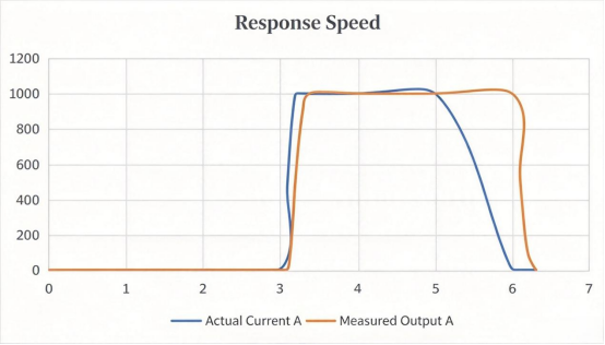
(Figure 2-1 | Response lag: The actual current has already changed, but the measurement signal has not yet caught up.)
The second point concerns the stability of the zero-point, one must not mistake measurement drift for actual equipment abnormality. This is particularly critical in predictive maintenance. Prediction often involves identifying subtle, gradual shifts within long-term data—such as the gradual degradation of a component or the appearance of an unwanted current component. Such assessments demand high zero-point stability. If the measurement point’s zero-point drifts with temperature, the data will change gradually even though the equipment is functioning normally, a model might then misinterpret this sensor drift as an equipment fault, triggering a false alarm, or conversely, the drift might mask a genuine, minor anomaly. False positives and missed detections often stem from precisely this issue. CHIPSENSE current sensors excel in this regard.
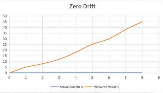
(Figure 2-2 | Zero drift: The device current remains constant, yet the measured value gradually drifts.)
The third point is that the readings must be accurate and linear, and the equipment itself cannot be affected by adding measurements. The power supply equipment is not only concerned about "measurement", but also about "whether the measurement is accurate" and "whether the measurement is costly". For high current main circuits in conventional power equipment as well as HVDC and SST systems, if a solution is adopted that requires the measured current to flow through the sampling element, additional voltage drop, power consumption and heat must be included in the design.Non-contact current sensors can obtain current information without cutting off the main circuit and avoid adding such series measurement components to the main circuit.
The combination of these three levels is actually one sentence: the current data fed to the AI must be able to keep up, stand firm, and read accurately, and the cost of obtaining this information must be small enough. CHIPSENSE current sensors all feature high linearity and excellent accuracy.
Why zero-flux closed-loop technology is inherently suited to serve as this "source of data."
To satisfy all three requirements simultaneously, one must consider how the current is actually measured. Several characteristics of closed-loop zero-flux technology align perfectly with the three challenges mentioned above.
Closed-loop Hall-effect like the CR8A current sensor of CHIPSENSE operate on a compensation principle: a feedback current is used to counteract the magnetic field generated by the primary current, thereby maintaining the magnetic core's operating point at a state of near-zero flux. When the current to be measured passes through the core, it generates a magnetic field; a compensation winding located on the other side of the sensor—driven by circuitry that monitors the flux detected by the Hall element—generates a real-time counter-current. This counter-current cancels out the primary magnetic field, constantly pulling the core's magnetic flux back to zero. The magnitude of this compensation current, scaled according to the winding turns ratio, provides a direct measure of the primary current.
This mechanism leads to several direct consequences. These are the specifications for the CHIPSENSE CR8A M12 current sensor.
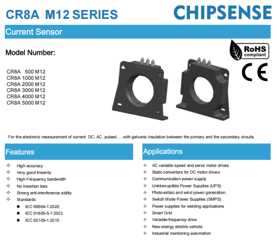
(Figure 3 | CHIPSENSE CR8A Series Current Sensor)
First, it offers rapid response and wide bandwidth. This is a real-time negative feedback process: as soon as the primary current changes, the compensation circuit acts immediately to counteract it, ensuring the magnetic core rarely remains in a magnetized state. Taking this CHIPSENSE current sensor as an example, its response time to a current step is under one microsecond, and it boasts a bandwidth of 100kHz, it can effectively keep pace with rapid fluctuations—such as those occurring during load switching or fault events within power converters, HVDC and SST hardware—ensuring the waveform fed into the model suffers no lag. This addresses the first critical requirement.
Second, the zero-point stability and linearity are inherently superior. Open-loop designs operate with the magnetic core carrying magnetic flux, meaning the output relies on the linearity of the magnetic material and the Hall element itself, issues such as residual magnetism following temperature fluctuations or high-current surges can arise, requiring extra attention to zero-point stability. Closed-loop compensation maintains the magnetic core's operating point near the zero-flux region, thereby significantly reducing reliance on nonlinear factors like magnetic hysteresis and residual magnetism compared to open-loop designs. The CHIPSENSE current sensor CR8A achieves an accuracy of 0.3% at the rated point and a linearity error of just 0.1%, such zero-point stability is equally vital for equipment intended for long-term operation.
The lower the zero-point drift of the measurement component itself, the less likely it is that slow variations in long-term data will be contaminated by measurement errors. This is particularly critical for systems requiring trend analysis and condition monitoring, including HVDC and SST assets under AI monitoring. Because the measurement point remains "stationary" across the entire temperature range, any slow changes detected by the model in long-term data are far more likely to originate from the equipment itself rather than from the measurement point drifting with temperature fluctuations. This addresses the second key requirement.
Finally, it employs non-contact primary-side measurement, since it does not require inserting components like sampling resistors in series with the main circuit, it avoids the additional voltage drop and power consumption associated with series-sampling schemes. With an insulation withstand voltage of 6kV and an impulse withstand voltage of 23kV, it provides true electrical isolation, which is highly valuable for high voltage scenarios such as HVDC and SST. This addresses the third key requirement. CHIPSENSE current sensor also happens to meet this requirement.
The strength of the closed-loop zero-flux technology lies not in a single standout specification, but in an operating principle that simultaneously satisfies four criteria: high-speed response ("keeping up"), stability ("standing firm"), accuracy ("reading correctly"), and efficiency ("low cost"). By serving as the data source at the very beginning of the AI analysis chain, CHIPSENSE current sensor ensures a solid foundation for the entire system.
IV. Rated Current vs. Measurement Range: Two Distinct Concepts
Ensuring data reliability involves addressing an issue often subject to confusion: the need to align the measurement range with the equipment's actual current distribution. It must be reiterated that rated current and measurement range are not the same thing.
They represent distinct concepts. Rated current corresponds to the sensor's specified operating conditions, whereas the measurement range defines the span of current values the sensor can effectively cover. Determining the relationship between the two requires consulting the specific model's datasheet and considering actual operating conditions, one cannot simply assume that operation above the rated value is restricted to short durations only. In fact, the design inherently allows for handling brief over-current events,which frequently occur in HVDC and SST transient working states. Taking CHIPSENSE CR8A 1000A model current sensor as an example: while the rated current is 1000A, the measurement range extends to ±1500A. Under normal continuous operation, the current should remain close to the rated value, while short-term peaks—such as those occurring during startup or sudden load fluctuations—fall within the broader measurement range without causing the signal to saturate or the reading to clip. This is specified in the datasheet for every CHIPSENSE current sensor.
This is particularly critical in AI applications, for algorithms relying on waveform characteristics—such as anomaly detection and state diagnosis for conventional power equipment as well as HVDC and SST hardware—short duration peaks and dynamic processes often contain vital information. If the measurement range is set too low, readings will clip during over current events, preventing the model from determining the peak magnitude or potentially causing it to miss key features, conversely, if the range is set too high, normal current occupies only a small fraction of the full scale, resulting in wasted resolution. Every CHIPSENSE technical engineer ensures the accuracy of the parameter data for this current sensor.

(Figure 2-3 | Insufficient measurement range: The waveform is clipped when the actual peak exceeds the measurement range.)
Therefore, the selection process follows two criteria: continuous current must align with rated current, and short-term peak current must remain within the measurement range. Specific peak values should be based on actual wave-forms measured from the equipment and control strategy, one cannot simply rely on generalized figures. To this end, CHIPSENSE has also introduced a professional selection guide and a customization form, making it easier to provide customers with current and voltage sensors that meet their specific requirements.
V. Sensors Only "Deliver the Truth Accurately" and Do Not Make Decisions for the Model
At this point, it is necessary to clearly define the boundaries to avoid overstating the situation.
Within the entire AI driven assessment chain covering generation, grid connected equipment, HVDC and SST platforms, the role of the current sensor is strictly defined: it is responsible solely for accurately, promptly, and stably converting the primary current into a signal for transmission. Products such as the CHIPSENSE current sensor focus entirely on this physical signal conversion. It does not make predictions or draw conclusions, nor does it decide whether maintenance is required or if power output needs adjustment. Such assessments are performed by controllers and higher level models based on the data, while critical decisions remain—for the foreseeable future—in the hands of professionals, this follows the well known paradigm of "AI assisted, human led decision making." CHIPSENSE acknowledges that AI is profitable, but recognizes that drawbacks come along with it. Current sensors cannot have even the slightest error.
CHIPSENSEis a national high-tech enterprise that focuses on the research and development, production, and application of high-end current and voltage sensors, as well as forward research on sensor chips and cutting-edge sensor technologies. CHIPSENSEis committed to providing customers with independently developed sensors, as well as diversified customized products and solutions.
“CHIPSENSE, sensing a better world!”
www.chipsense.net