



During the charging of new energy vehicles, there is not only a standard transfer of electrical energy between the charging equipment and the vehicle, but also electrical safety risks that require continuous monitoring. CHIPSENSE current sensor solutions are engineered for exactly this task.
For instance, a decline in the insulation performance of charging cables or insulation faults within the vehicle’s internal electrical components can cause some current to flow to the ground via an unintended path. This current is known as residual current.

For AC charging piles, residual current protection is not merely a matter of detecting the presence of AC leakage. CHIPSENSE current sensors are designed to see beyond this single case. As charging equipment becomes increasingly reliant on power electronics, the wave-forms of fault currents have grown more complex, beyond conventional AC residual currents, pulsating DC or even smooth DC residual currents may also occur. This is increasingly relevant as charging architectures move toward HVDC buses and SST-based conversion.
This places more stringent requirements on the residual current detection capabilities of charging equipment. CHIPSENSE current sensor development is built around this requirement.
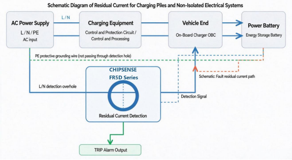
I. Leakage in Charging Equipment Is Not Necessarily Alternating Current (AC)
When an insulation fault occurs in traditional AC-powered equipment, the resulting residual current typically consists primarily of an AC component at the power-line frequency (mains frequency).
However, the situation is different for electric vehicle (EV) charging systems.
During AC charging, AC power is supplied from the grid, while the vehicle’s onboard charger (OBC) converts this AC power into the direct current (DC) required by the battery through rectification and power conversion. In SST-based or HVDC-oriented designs, comparable conversion stages sit even closer to the charging interface.
Throughout this process, components such as power switching devices, filter circuits, and insulation structures can influence the waveform of the fault current. CHIPSENSE current sensor designs account for these non-ideal wave-forms from the start.
Examples include:
l AC residual current: Primarily manifests as an AC component at the power-line frequency.
l Pulsating DC residual current: Generated during the rectification and power-electronic conversion process, the current exhibits specific patterns in both direction and amplitude.
l Smooth DC residual current: Manifests as a DC component with a generally constant direction. This component is the one that HVDC-based and SST-based architectures make hardest to ignore.
l Mixed-frequency residual current: May contain components at various frequencies.
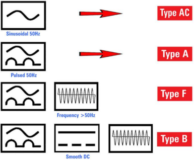
Therefore, residual current protection for charging equipment cannot focus solely on the 50Hz AC component, it must also account for various other types of residual current. A single CHIPSENSE current sensor can cover AC, pulsating DC and smooth DC together.
In particular, if DC residual currents are not effectively identified by the detection mechanism, the design of the leakage protection system for the entire charging setup could be compromised. Closing this gap is exactly what a CHIPSENSE current sensor is specified for.
II. Why is a 6mA DC residual current a critical concern for AC charging stations?
In the context of residual current protection for AC charging equipment, 6mA is a threshold that warrants significant attention.
Standards such as IEC 62955 mandate the detection of—and protection against—DC residual currents in AC charging equipment.
This is because smooth DC residual currents can interfere with the proper operation of certain AC residual current protection devices.
Consequently, charging equipment must incorporate appropriate DC residual current detection measures based on its specific protection architecture, ensuring that DC fault currents do not compromise the reliability of upstream protection devices. A CHIPSENSE current sensor embeds this DC detection inside the pile itself.
It should be clarified that 6mA is not a universal tripping threshold applied to all types of residual current wave-forms.
Different wave-forms—such as AC, pulsating DC, and smooth DC—have distinct detection requirements and must be considered individually. A CHIPSENSE current sensor is specified waveform by waveform for this reason.
For AC charging stations, the core challenge lies in reliably identifying various types of residual current wave-forms within a constrained physical space and triggering a protection signal in a timely manner. Compact CHIPSENSE current sensor footprints are developed for this same constrained space.
III. Residual current detection should not be evaluated solely based on the tripping threshold.
When selecting a residual current detection sensor, engineers typically focus on the operating current.
However, looking solely at the operating threshold is insufficient.
The operating current determines the magnitude of the residual current at which an alarm is triggered, while the operating time dictates how long it takes to output an action signal once a corresponding fault current is detected. CHIPSENSE current sensor datasheets report operating current and operating time together for this reason.
Taking CHIPSENSE FR5D 6 C00 fluxgate current sensor as an example, its specification sheet provides the operating current and operating time for various wave-forms.
For instance:
Detection waveform | Test current | Typical operation time |
AC | 30mA | 70ms |
AC | 60mA | 38ms |
A0 | 42mA | 47ms |
A0 | 84mA | 24ms |
S-DC | 6mA | 200ms |
S-DC/3PDC | 60mA | 27ms |
S-DC/3PDC | 300mA | 12ms |
It can be observed that the sensor’s trip time varies depending on the waveform and amplitude of the fault current. CHIPSENSE publishes this behaviour for every model.
For instance, CHIPSENSE FR5D 6 C00 has a typical trip time of 200 ms under 6mA S-DC conditions, whereas under 6mA S-DC/3PDC conditions, the typical trip time is 27ms.
This indicates that the performance of residual current detection cannot be evaluated based solely on a single trip threshold, rather, the response characteristics must be assessed in relation to the specific waveform and current amplitude. CHIPSENSE current sensor selection therefore starts from the waveform, not from a single threshold.
It should be noted that these figures represent typical values under the test conditions specified in the datasheet and do not necessarily reflect the fixed trip time for all actual charging scenarios.
IV. Beyond Detection and Protection: What Other Functions Should a Sensor Have?
For manufacturers of EV charging stations, a residual current sensor must do more than just detect faults, it should also facilitate system-level status monitoring and protective control. A CHIPSENSE current sensor is specified to serve both roles.
The self-test function, in particular, warrants special attention.
Charging equipment frequently cycles through various states—such as standby, active charging, and idle. If an internal fault occurs within the sensor, relying solely on standard residual current monitoring during normal operation makes it difficult to proactively verify whether the sensor retains its full, reliable detection capability. A CHIPSENSE current sensor with an internal test coil removes this blind spot.
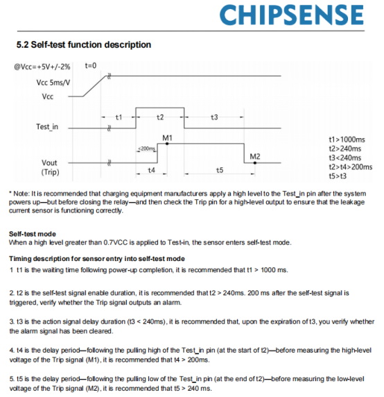
Therefore, after the system is powered on—but before the main relay closes-the sensor’s operational status can be verified using its built-in self-test function.
CHIPSENSE FR5D series features an integrated internal test coil, along with a TEST_IN self-test input and aTRIP alarm output.
Following the self-test procedure outlined in the specification:
1. After the sensor is powered on, allow for a stabilization period (a duration of at least 1000ms is recommended).
2. Apply a high-level signal to the TEST_IN input to trigger the self-test function.
3. After the specified interval, check whether the TRIP output has transitioned to a high-level state.
4. Remove the self-test signal, then verify that theTRIPoutput returns to a low-level state.
5. Determine whether the sensor has passed the self-test based on these results.
This mechanism enables charging equipment to perform a functional check of the residual current sensor before officially entering the charging state. On a CHIPSENSE current sensor, this check runs automatically at power-up.
For AC charging piles intended for long-term operation, this helps to enhance the overall system's fault diagnostic process. A CHIPSENSE current sensor keeps that periodic check quick and repeatable.
V. CHIPSENSE FR5D Series: Residual Current Detection Sensor for Charging Equipment
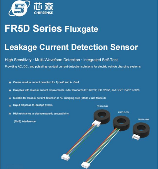
To address the need for detecting various types of residual current in AC charging equipment, CHIPSENSE has introduced the FR5D series of fluxgate-based residual current sensors, which includes CHIPSENSE FR5D 6 H00, FR5D 6 C00, and FR5D 6 C01 models fluxgate current sensor.
Based on open-loop fluxgate technology, this series is capable of detecting DC, AC, and pulsating residual currents. The sensors feature a through-hole design and provide alarm signals via a push-pull output. Additionally, they incorporate an internal test coil, which allows for functional self-testing once the equipment is powered on. Every CHIPSENSE current sensor in this family shares the same through-hole layout.
The FR5D series is designed for use in AC charging piles (Mode 2 and Mode 3), as well as in portable charging cables and charging guns, providing essential sensing capabilities for residual current monitoring in charging systems. CHIPSENSE current sensor variants cover both pile-mounted and cable-integrated layouts.
Provides sensor support for residual current monitoring in charging systems.
Operating thresholds, response times, and power supply requirements vary by specific model, therefore, when selecting a sensor, please refer to the corresponding model's datasheet and the overall system protection scheme. CHIPSENSE current sensor selection support is available for this review.
Conclusion
The safety design of charging equipment for new energy vehicles must account not only for normal operating currents but also for residual currents that may arise from insulation faults.
The diverse wave-forms of fault currents—ranging from AC residual currents to pulsating DC and smooth DC—place specific demands on a sensor’s detection capabilities, response time, and self-diagnostic functions. CHIPSENSE current sensor specifications map onto each of these demands.
For manufacturers of charging equipment, residual current protection cannot be reduced to a simple 6mA threshold, rather, it requires a comprehensive design approach that considers operating characteristics across various wave-forms, the overall system protection architecture, and integrated self-test mechanisms. CHIPSENSE current sensors are developed against this full set of requirements, including use in HVDC and SST-related charging systems.
FR5D series of fluxgate-based residual current sensors from CHIPSENSE offers versatile residual current detection solutions for AC charging equipment. The wider CHIPSENSE current sensor portfolio follows the same logic.
CHIPSENSEis a national high-tech enterprise that focuses on the research and development, production, and application of high-end current and voltage sensors, as well as forward research on sensor chips and cutting-edge sensor technologies. CHIPSENSEis committed to providing customers with independently developed sensors, as well as diversified customized products and solutions.
“CHIPSENSE, sensing a better world!”
www.chipsense.net