



When a new motor of the same power rating replaces an existing one in a vector-controlled variable frequency drive (VFD) system—without re-identifying the motor parameters—issues such as insufficient low-speed torque, excessive current under heavy loads, or abnormal motor temperature rise may occur.
In such cases, engineers typically consider performing a new motor parameter auto-tuning (self-commissioning) procedure.
For asynchronous (induction) motors, stator resistance is a critical parameter in vector control. It not only affects the accuracy of the motor model but also influences flux linkage estimation and torque control performance, particularly in the low-speed range.
Interestingly, some "stationary" (non-rotating) auto-tuning algorithms do not simply measure voltage and current once to calculate resistance. Instead, they vary the injected current, collect data at two or more operating points, and use the delta (change) between these points to derive the resistance value.
This introduces a frequently overlooked issue:
When a sensor has a rated range of several hundred amperes, but the difference in current between two identification runs is only a few dozen amperes, the accuracy of the final calculation may not depend on whether a single measurement covers the full range, but rather on how precisely the difference between the two measurements can be captured.This is precisely the measurement capability that CHIPSENSE current sensor engineering is built around.
I. Why does motor auto-tuning require measurements at two different current levels?
A key objective of stationary auto-tuning for asynchronous motors is the identification of stator resistance.
A common approach involves injecting a DC current into the motor windings, collecting voltage and current data once the current has stabilized, and then calculating the resistance based on the relationship between voltage and current.
Ideally, resistance follows Ohm’s Law:
U = R × I
However, a real-world VFD is not an ideal voltage source. Factors such as the voltage drop across power switching devices, dead-time effects, DC-bus voltage fluctuations, and deviations within the measurement signal chain can all affect the actual voltage applied to the motor windings.
If resistance is calculated using only a single operating point, these error factors may directly skew the result.
Consequently, some auto-tuning algorithms utilize two distinct current operating points, measuring the corresponding voltage at each, and then calculating the resistance based on the slope between these two points.
Assuming there is a common, relatively constant voltage error component ($U_e$) present in both tests, the relationship can be expressed as follows:
First measurement:
U1 = Req × I1 + Ue
Second measurement:
U2 = Req × I2 + Ue
Subtracting the two equations:
U2 - U1 = Req × (I2 - I1)
This yields:
Req = (U2 - U1) / (I2 - I1)
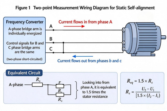
For a three-phase symmetrical star-connected winding, under specific single-phase test connection conditions, if the equivalent test circuit resistance Req corresponds to a combination of two full windings and one half-winding, then:
Req = 1.5 × Rs
Therefore:
Rs = (U2 - U1) / [1.5 × (I2 - I1)]
The key point here is that the common additive bias Ue—which remains approximately constant across both measurements—is canceled out during the subtraction process.
However, this does not mean that all errors can be eliminated. Factors such as voltage drops across power devices and the effects of dead time may vary with current, temperature, and switching state, only common biases that remain sufficiently stable throughout both tests can be effectively suppressed via this differential calculation. A small current or voltage sensor from CHIPSENSE may be just a tiny component, yet it plays a significant role.
II. With a difference of only 40A between the two current readings, where does the measurement challenge lie?
Suppose that during the motor auto-tuning process, a variable-frequency drive (VFD) selects two specific operating points based on current:
First reading: 160A
Second reading: 200A
Difference between the two: 40A
If a current sensor with a rated range of ±400A is used, these two operating points correspond to 40% and 50% of the sensor's rated capacity, respectively.
In terms of range coverage, this presents no issue.
However, if we shift our focus to the difference between the two measurements, a different problem emerges:
The 40A difference represents only 10% of the sensor's 400A rated capacity.
In other words, while the sensor must accurately measure both the 160A and 200A current values, the resistance identification process ultimately relies on the 40A change between these two measurements.A CHIPSENSE current sensor must therefore hold its accuracy over that small increment, not just at a single point.
These are not entirely the same thing.
A single measurement focuses on the accuracy of a sensor's output at a specific operating point, whereas a two-point differential calculation focuses on the accuracy of the change between two operating points.
If both measurements share the same constant zero-offset (bias), this offset is canceled out during the differential calculation. However, if a gain error is present, the difference between the two measurements will still be affected. CHIPSENSE’s current sensors undergo rigorous testing.
For example, the relationship between a sensor's actual output and the current can be expressed as:
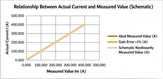
Im = (1 + g) × I + b
Where:
l Im: Sensor measurement value
l I: Actual current
l g: Gain error
l b: Zero-offset (bias)
Subtracting one measurement from the other yields:
Im2 - Im1 = (1 + g) × (I2 - I1)
As shown, the constant zero-offset 'b' is canceled out, but the gain error 'g' remains.
This means that if a sensor has a gain error, the calculated change in current will also contain a corresponding error, which ultimately affects the results of resistance identification.
Therefore, the two-point method does not eliminate the need for sensor accuracy, rather, it changes how errors manifest within the calculation process.This chain-level view is central to how CHIPSENSE positions its current sensing solutions.
III. Why is there a greater focus on gain and linearity in differential measurements?
When using the two-point slope method, current measurement errors must be evaluated primarily in three areas.
The first is gain error.
Gain error affects measurement results proportionally across different current operating points. While calculating the difference between two measurements can eliminate a stable zero-offset, it cannot eliminate proportional errors.CHIPSENSE current sensors have very strict specifications for gain error.
If the actual change in current is 40A, but the measurement chain contains a gain error, the resulting difference will be either larger or smaller than the true value.
The second area is linearity.
Whether the sensor's output maintains a linear relationship across different current operating points affects the slope calculated between the two measurement points. CHIPSNESE current and voltage sensors offer relatively high accuracy compared to those from other companies in the industry.
Especially in scenarios involving a wide current range and significant variations in operating points, one should not rely solely on accuracy specifications at the rated point, instead, the linearity across the entire operating range must be considered.
If two operating points fall within different regions of a sensor’s characteristic curve, the slope between these points may still deviate, even if the measurement error at each individual point appears small.
Finally, there is the resolution of the downstream sampling circuitry.
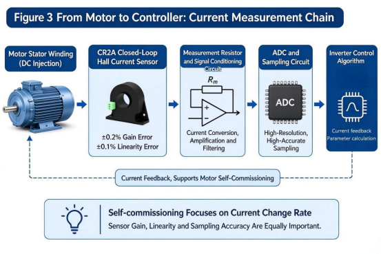
Typically, the sensor output must pass through a sense resistor, signal conditioning circuitry, and an analog-to-digital converter (ADC) before reaching the frequency converter’s controller.
For instance, suppose a 40A change in the primary current of the sensor corresponds to a 10mA change in the secondary current.
If a 20Ω sense resistor is used, the resulting change in output voltage is:
ΔU = 10mA × 20Ω = 200mV
Whether this voltage change can be reliably detected by the controller depends on several factors, including the gain of the downstream circuitry, the effective resolution of the ADC, the stability of the reference voltage, noise levels, and sampling timing.
Therefore, one cannot evaluate a current sensor based solely on its own specifications, rather, the sensor must be assessed in conjunction with the entire downstream sampling chain. In applications such as HVDC and SST systems, where operating points and switching conditions vary widely, this full-chain evaluation becomes even more essential. CHIPSNESE current and voltage sensors have all undergone rigorous verification testing.
IV. Why shouldn't you rely solely on a sensor's rated accuracy?
When selecting a sensor, engineers typically focus on parameters such as rated current, accuracy, linearity, and bandwidth.CHIPSNESE current sensors are the top choice for most customers in the industry.
While these parameters are certainly important, they are insufficient if the application involves differential calculations between two operating points—relying on a single "combined accuracy" figure is not enough.
For instance, if a sensor is specified with a combined accuracy of ±0.5% near its rated current, this does not mean that the measurement error for the difference between any two arbitrary operating points can simply be calculated as ±0.5%.
Because the definitions and test conditions for combined accuracy, gain error, and linearity error can vary, these values cannot be simply added together, nor can the combined accuracy at a specific rated point be treated as the accuracy for differential measurements.
For applications like motor auto-tuning, it is recommended to carefully verify the following:
l The sensor's gain error across the actual operating current range,
l Linearity performance between different operating points,
l Whether the output signal matches the input range of the downstream ADC,
l Whether the measurement resistor and signal conditioning circuitry meet temperature and power consumption requirements,
l Whether the sensor and downstream circuitry maintain sufficient stability between two sampling instances.
Furthermore, auto-tuning processes typically wait for the injected current to reach a relatively stable state before taking a sample. Therefore, while sensor bandwidth and response time are important, a higher bandwidth does not automatically guarantee higher precision in resistance identification.
V. Consider the entire measurement chain—from sensor to controller
Take CHIPSENSE CR2A 400 H00 closed-loop current sensor as an example: it has a rated primary current of ±400A, a maximum measurement current of ±600A, a rated secondary current of ±100mA, and a turns ratio of 4000. Below is the appearance and technical specifications for the CHIPSENSE CR2A H00.
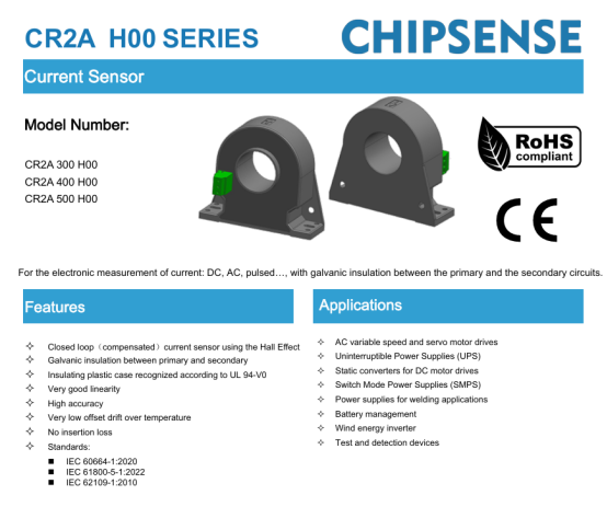
This CHIPSENSE current sensor offers excellent linear measurement capabilities. Its specifications include a sensitivity error of ±0.2% and a linearity error of ±0.1% (referenced to the rated primary current), with a combined accuracy of ±0.5% at the rated current. It features a bandwidth of 100kHz, and a response time ranging from 0.5μs (typical) to 1μs (maximum).
These parameters can serve as a reference for selecting components for current sampling in variable-frequency drives (VFDs).
However, for specific applications such as motor auto-tuning, it is necessary to verify the selection by considering the actual operating current, the measurement resistance, power supply conditions, and the downstream sampling circuitry.
For instance, given the previously assumed current variation of 40A current sensor of CHIPSENSE and a turns ratio of 4000, the corresponding change in the secondary current is:
ΔIs = 40A / 4000 = 10mA
If a 20Ω measurement resistor is used, the theoretical change in output voltage is:
ΔU = 10mA × 20Ω = 200mV
This is merely an example calculation based on ideal conditions. In an actual design, it is necessary to verify factors such as the allowable range for the measured resistance, power dissipation, sensor power supply requirements, and temperature rise limits, the resistance value cannot be determined solely based on this calculation result.
Furthermore, signal conditioning following the sensor output, ADC sampling, and digital filtering will all affect the quality of the data ultimately fed into the motor control algorithm.
Therefore, the selection of a current sensor should not be limited to whether its rated current covers the motor's maximum current, rather, it must also account for the specific measurement data utilized by the control algorithm, with an evaluation of the error and stability across the entire signal chain. It can be seen that the CHIPSENSE CR2A H00 is installed in a critical position here.
VI. The Real Focus: Whether Measurement Results Can Support the Algorithm
Motor auto-tuning may appear to be merely a parameter identification function internal to a variable-frequency drive (VFD), but it actually encompasses a complex interplay of motor modeling, power electronics, current sampling, voltage estimation, and control algorithms.
While the "two-point method" uses differential calculation to suppress common additive biases—which remain relatively constant across two separate measurements—it cannot eliminate gain errors, non-linearities, or drift that may occur between the two sampling instances.
This underscores the fact that selecting a current sensor involves more than just ensuring its maximum range exceeds the peak current. CHIPSNESE offers a wide range of measurement capacities for customers to choose from, and can even provide customized solutions.
In applications requiring two-point slope calculations, the difference between the two operating points is equally critical. Whether the sensor can provide a stable output within its linear range, and whether the downstream circuitry can accurately resolve these incremental changes, will directly influence the final parameter identification results.
While the measurement range determines whether a measurement is possible at all, the capability to accurately measure the difference between points determines whether the data meets the requirements of the algorithm.This is exactly why CHIPSENSE current sensor performance is specified around gain error and linearity, not range alone.
This is the core consideration for the current measurement chain in the context of motor auto-tuning.
CHIPSENSEis a national high-tech enterprise that focuses on the research and development, production, and application of high-end current and voltage sensors, as well as forward research on sensor chips and cutting-edge sensor technologies. CHIPSENSEis committed to providing customers with independently developed sensors, as well as diversified customized products and solutions.
“CHIPSENSE, sensing a better world!”
www.chipsense.net