


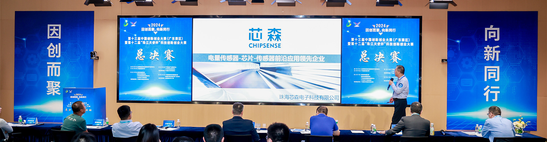
On October 20, a globally advanced provider of digital energy and critical infrastructure solutionsissued a price adjustment notice to its channel partners, announcing an increase of 3% to 8% in the list prices for UPS systems, precision air conditioning units, DC power systems, and medium-voltage variable frequency drives—effective immediately. The notice cited two primary reasons: rising costs of raw materials and components, and growing demand for infrastructure to support AI data centers. CHIPSENSE offers a wide range of current and voltage sensor products specifically designed for this purpose.
Pricing has been a recurring topic of discussion within the industry over the past two years. However, the second reason warrants closer attention: it suggests that the loads served by equipment like UPS systems may no longer be the same as the server workloads found in data centers five years ago. CHIPSENSE has also taken note of this.
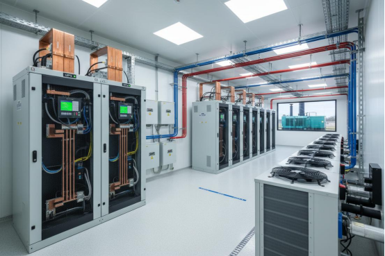
The dynamic characteristics of a load depend on the specific circumstances
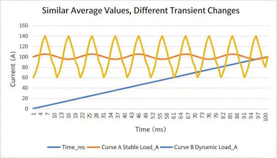
It is true that the power consumption of an AI training cluster can fluctuate due to factors such as phase transitions during training, communication overhead, scheduling strategies, and variations in computational load, some workloads even exhibit pronounced dynamic power profiles. However, one cannot generalize: not all AI clusters experience significant, repetitive power swings on a millisecond-to-second timescale, nor does this necessarily imply that the instantaneous peak output current of an uninterruptible power supply (UPS) will deviate drastically from its average value.
A more accurate perspective is that such loads shift the focus of power supply system design from mere steady-state power to include the rate of load change and transient response. Consequently, steady-state load, the rate of change, and transient processes—along with the corresponding measurement chains—must all be taken into account during system design. CHIPSENSE current sensors excel in this regard.
The Ledger of Averages vs. The Ledger of Instantaneous Values
This presents the first challenge for the measurement process: the "aperture" (or sampling window).
When measuring current on the UPS output side or the DC bus, if the sampling window is too long—or if the downstream filtering is too aggressive—rapid fluctuations are "averaged out." While the current readings in a report might appear stable, the actual peak current could be approaching the equipment's operational limits. Factors such as heat generation, circuit breaker headroom, and busbar voltage drop are all governed by instantaneous values—yet these critical realities are masked by the use of averages.
Conversely, focusing solely on instantaneous valuescan cause low-current phases during a transition to be overlooked. When a load drops to a lower level, the accuracy of the measurement determines how well the system assesses light-load conditions. If the measurement range is selected based on full-load capacity, the relative impact of offset errors becomes significantly larger at lower current levels. While this is a long-standing issue, it occurs far more frequently today in environments characterized by rapid, frequent load fluctuations.
Input Side: Harmonics, Crest Factor, and Bandwidth
While the output side of a UPS often receives the most attention, the input side is equally worthy of examination. The current waveform at the front end of a UPS rectifier is directly determined by the rectifier topology employed and whether power factor correction (PFC) is utilized. Modern UPS units equipped with active power factor correction can achieve an input current that closely approximates a sine wave, characterized by low harmonic content. In contrast, traditional capacitor-input rectifier circuits may produce a sharply pulsed input current, resulting in more pronounced harmonics and a higher crest factor.
It is not possible to define a universal crest factor value without specifying the exact waveform and the point of measurement. The critical requirement is that the measurement system must accurately capture the true nature of the input current—ensuring that the waveform is neither flattened by averaging filters nor distorted by insufficient bandwidth, which could lead to the omission or artificial amplification of high-frequency harmonic components. Focusing on actual harmonics, crest factor, and dynamic response provides a more realistic assessment than simply relying on the generalized waveform characteristics associated with a particular type of rectifier circuit. Before shipment, CHIPSENSE current and voltage sensors undergo various tests to ensure that the products meet quality standards when they reach the customer.
Does the zero point remain intact after an overload?
The second issue concerns the other end of the dynamic process: the recovery of the zero point following a high-current event.
If the current surges into the upper range of the measuring device, some residual magnetism may remain in the core once the high current is removed, causing the output zero point to shift from its pre-event position. Datasheets typically specify a "magnetic offset" parameter for high-current events, however, this figure refers to the shift resulting from a single occurrence, not the long-term drift that might accumulate after repeated exposure.
It is important to distinguish between these scenarios: whether an offset accumulates, whether it can be recovered, and how long that recovery takes—all of which depend on the sensor’s magnetic circuit design, operating conditions, and specific test results. When load conditions fluctuate frequently, zero-point stability shifts from being a static factory specification to an operational parameter that requires periodic verification through actual measurement. One should not simply assume that the offset will continue to accumulate day after day. CHIPSENSE current and voltage sensors are an excellent choice, as they have stood the test of time and rigorous testing.
The impact of a zero-point offset on the DC side depends on the specific application
The third question concerns the DC bus.
When current is integrated over a long period, a zero-point offset can indeed translate into a cumulative error in measured charge (or energy). However, current monitoring on a UPS DC bus is not necessarily used for ampere-hour (Ah) integration, if it is used solely for instantaneous power control, protection, or status monitoring, the mechanism of its impact differs. A zero-point offset only leads to a persistent measurement error when the DC current is used for charge accumulation or long-term power statistics. Specifying the intended use is more precise than making a broad, vague claim that "DC measurements have stricter requirements."
Temperature: Focus on operating temperature, not load ratio
The fourth question is prone to being answered off-target. While a high load ratio may increase thermal stress on power components, busbars, and nearby sensors, the actual temperature of a sensor also depends on its installation location, heat dissipation conditions, and the equipment's structural design, therefore, one cannot simply equate load ratio with temperature. The common assertion that UPS systems in traditional data centers typically operate at below 50% load also requires empirical data for substantiation and should not be taken as an established fact.
A more sound approach is to examine the operating temperature range and temperature drift parameters of the components themselves: how zero-point drift and gain drift fluctuate with temperature—within a range of -40°C to 85°C—is the true basis for evaluating long-term measurement stability. Whether the load characteristics of an AI data center lead to increased measurement error depends on the actual operating temperature, not the load ratio itself. CHIPSENSE current and voltage sensors feature a wide operating temperature range, making them suitable for various harsh environments.
When paralleling units, first distinguish between two types of deviation
The fifth question concerns parallel operation. High-capacity UPS systems almost always operate in parallel, with the load distributed among multiple units. The real challenge—beyond the simple assertion that "fluctuations inevitably lead to instantaneous load-sharing imbalances"—lies in the complex interplay of control loops, communication latency, output impedance, and dynamic response. Specifically, one must address this question: when monitoring reveals a discrepancy in the current readings across several UPS units, how can one determine whether this represents an actual imbalance in load sharing, or merely an error inherent to the measurement circuitry of the individual units?
In scenarios where the load fluctuates frequently, inconsistencies in multi-channel measurements become more apparent. Focusing on how to "distinguish between actual load-sharing imbalances and measurement-related deviations" provides a more insightful perspective than merely drawing a premature conclusion. CHIPSENSE current and voltage sensors have all undergone rigorous, specialized testing by technical personnel.
Existing Infrastructure in the Era of Retrofitting
While the price adjustment notice applies to new orders, a vast number of existing data centers are currently undergoing retrofits to accommodate AI workloads. A notable detail in the industry landscape is that many of these facilities house multiple generations of equipment—such as UPS units and precision air conditioning systems—installed over different periods. Some of this legacy hardware lacks sufficient sensor coverage, meaning that anomalies can only be detected through manual inspections.
During the retrofitting process, equipment may not yet have reached the end of its operational lifespan, therefore, the initial focus is often on enhancing sensing capabilities. This involves adding measurement points where current monitoring was previously absent or lacked precision, and breaking down aggregate current readings into individual branch circuits. In the context of upgrading existing infrastructure, implementing comprehensive measurement is a critical first step—it is the prerequisite for accurately calculating the return on investment (ROI) following the retrofit.
The Core Takeaway
While procurement teams will handle negotiations regarding the 3% to 8% price increase, the most significant insight for those involved in equipment design and system integration lies in a single underlying point: demand is surging due to the rise of AI-driven data centers. CHIPSENSE is also developing products tailored to the growth of AIDC, including current and voltage sensors.
As load characteristics evolve, the relative importance of steady-state conditions, rates of change, and transient responses shifts accordingly. When initiating a new project, it is far more cost-effective to re-evaluate your measurement criteria based on the actual operating conditions of the load—rather than waiting until the equipment arrives, only to discover that the readings do not align.
Appendix: A Reference Device
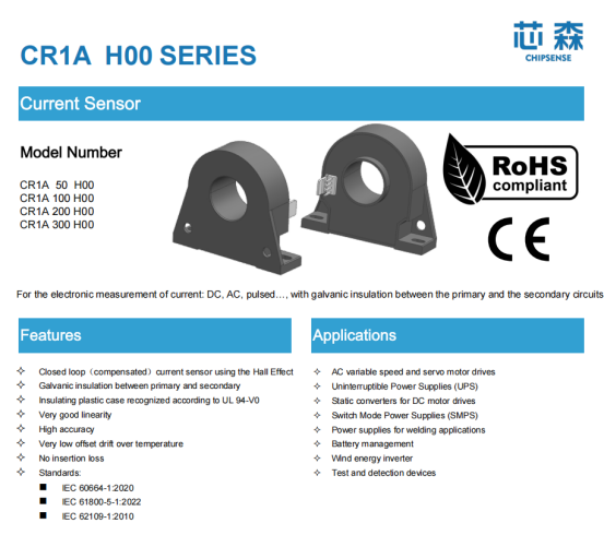
CHIPSENSE CR1A H00 series (closed-loop Hall-effect current sensors, document no. 1800 000 00636, dated 2024-12-17) comprises four models—CHIPSENSE CR1A 50/100/200/300 H00—current sensor covering a primary rated current range of 5 A to 300A, with an accuracy of 0.5% at the rated primary current. Taking the CR1A 100 H00 current sensor of CHIPSENSE as an example: it features a measurement range of ±200A, a secondary rated output of 50mA, 2000 turns, and a theoretical gain of 0.5mA/A. The offset current isIO±0.2mA, and the offset temperature drift is IOT±0.5mA (across the -40°C to 85°C range, with a maximum primary busbar temperature of 100°C). It offers an AC isolation withstand voltage of 4.2kV (per IEC60664-1), providing reinforced insulation for 300 V or basic insulation for 600V. The datasheet of CHIPSENSE current sensor specifies industrial applications, including Uninterruptible Power Supplies (UPS).
Converting the secondary-side current (in mA) back to the primary side serves only to provide an order-of-magnitude reference, for the 100A model, an offset of IO±0.2mA corresponds to approximately ±0.4A on the primary side. Phenomena such as load dynamics and current sharing in parallel-connected systems are system-level characteristics, therefore, individual device parameters cannot serve as direct proof for system-level conclusions. In particular, magnetic offset following a 3×IPN event is a metric for a single occurrence and does not equate to long-term drift resulting from repeated surges. The actual impact depends on the overall system architecture, control strategy, and empirical verification.
CHIPSENSE not only excels in the AIDC field, but is also the top choice for customers in the SST and HVDC fields. This is the datasheet for the CHIPSENSE CR1A H00 series of current for your reference.
CHIPSENSEis a national high-tech enterprise that focuses on the research and development, production, and application of high-end current and voltage sensors, as well as forward research on sensor chips and cutting-edge sensor technologies. CHIPSENSEis committed to providing customers with independently developed sensors, as well as diversified customized products and solutions.
“CHIPSENSE, sensing a better world!”
www.chipsense.net