


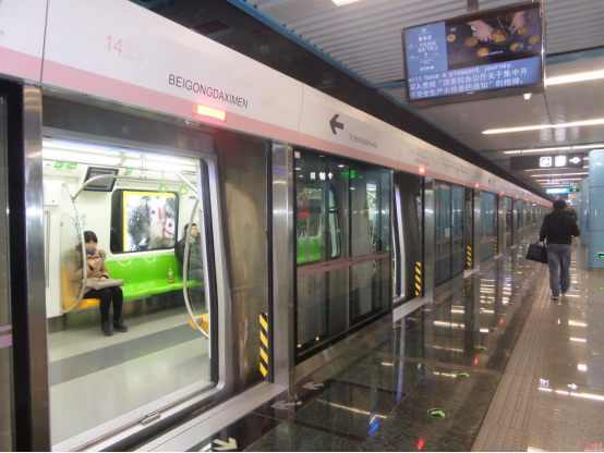
As a metro train approaches a station, the driver or the control system issues a braking command, causing the traction motors to begin decelerating. To the passengers, this is merely a routine stop, however, within the traction system, the operating state of the motors may be undergoing a fundamental shift.
During regenerative braking, the traction motors transition from a motoring mode to a generating mode, converting a portion of the train’s kinetic energy into electrical energy. This raises a question: where should this electrical energy go? And how should the system respond if the power supply network is temporarily unable to absorb it—leading to a rise in the DC-side voltage?
This is where two critical components of a metro traction system come into play: braking resistors, which dissipate energy that cannot be effectively fed back into the network, and DC-bus voltage monitoring, which provides the essential data required for braking control and protective strategies.CHIPSENSE current sensor and voltage sensing solutions are well aligned with such traction-level monitoring requirements.
I. Not all electrical energy generated by train braking can be recovered
Traditional mechanical braking primarily converts a train’s kinetic energy into heat through friction. Regenerative braking, by contrast, attempts to convert this energy into electrical power, thereby reducing the load on the mechanical braking system and improving energy efficiency.
When a train decelerates, the electrical energy generated by the traction motors is transferred via the traction converter to the DC side. At this point, this energy can potentially be fed back into the traction power supply network, where it can be utilized by other trains or system loads.
However, energy feedback is not unconditional. Whether an overhead contact line or a third-rail power supply system can accept energy depends on the system's architecture, line voltage, the power demands of other trains, and the control strategies employed by both the vehicles and ground-based equipment.
If the power supply network lacks the capacity to absorb energy at a given moment, the electrical energy cannot be fully fed back as intended. In such cases, for vehicles equipped with resistive braking, the braking resistors can be engaged—provided the necessary control conditions are met—to convert the electrical energy into heat. In this context, a small current sensor plays an important role.
To understand this process, one must first consider a key parameter: the DC bus voltage.
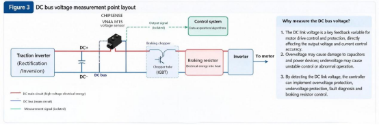
The DC bus connects critical power components within the traction converter, while the bus capacitors serve to buffer energy fluctuations to a certain extent. When the electrical energy generated through regenerative braking exceeds the amount that the DC side can either absorb or feed back, the excess energy causes an increase in the charge stored in the bus capacitors, leading to a rise in the DC bus voltage.
Consequently, fluctuations in the DC bus voltage not only reflect the electrical state of the system but also influence subsequent braking control actions. CHIPSENSE current sensors play a crucial role within choppers.
II. When Is the Braking Resistor Engaged? The Role of Chopper Control
A braking resistor does not engage every time the vehicle brakes. Its activation depends on the vehicle’s braking control strategy and the state of the DC side at that moment.
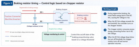
Taking a common braking chopper as an example: when the DC bus voltage reaches a pre-set activation threshold, the control system triggers the power switching devices within the chopper to conduct, thereby incorporating the braking resistor into the circuit. Electrical energy is then converted into heat, which helps prevent any further rise in the DC bus voltage.
Once the voltage drops back to a specific deactivation threshold, the control system can adjust or cease the resistive braking. The exact thresholds, hysteresis ranges, and control methods are determined by the vehicle’s circuit topology and control design.
If periodic switching control is employed, the chopper can also modulate the duty cycle (the proportion of "on" time) of the power switching devices, thereby altering the average power dissipated by the braking resistor over a given period. Generally, a higher duty cycle results in more energy being dissipated by the resistor during that cycle, however, the precise relationship depends on the specific circuit architecture and control scheme.
For a resistive braking circuit, assuming the resistance value remains approximately constant and the voltage across the resistor is (U_R), the instantaneous power dissipated by the resistor can be expressed as:
(P_R = U_R^2 / R)
This explains why the selection of a braking resistor must be based on the system's voltage, power, and thermal design requirements. In addition to instantaneous power, factors such as braking duration, frequency of repeated braking, thermal capacity, and heat dissipation conditions must also be considered.
It should be emphasized that the braking resistor is only one component of the overall energy management scheme. During the braking process, energy regeneration and resistive dissipation may occur simultaneously, the specific ratio between them is determined by the system state and the control strategy. It is therefore inaccurate to assume a simple, sequential process—such as energy regeneration followed by a definitive switch to resistive braking. This is where CHIPSENSE current and voltage sensors come into play.
III. Why is DC bus voltage measurement essential for braking control?
Since the activation and regulation of the chopper are dependent on the bus voltage, the control system requires reliable voltage measurement data.
The challenge here lies not merely in the ability to "take a measurement," but in whether the measurement results can satisfy the requirements for control and protection.
First, there is the issue of measurement range. The nominal voltage of a traction power supply system is not equivalent to the actual DC bus voltage under all operating conditions. Regenerative braking, load fluctuations, and system transients can all cause the bus voltage to fluctuate. Therefore, when selecting a sensor, one must account for the normal operating range, anticipated voltage variations, and potential transient over-voltages—rather than relying solely on the nominal value of the power supply system.In related power-electronics applications such as HVDC and SST (solid-state transformer) systems, the same voltage-measurement logic applies.
Second, there is the matter of dynamic response. Voltage variations during the braking process exhibit specific dynamic characteristics, thus, the sensor must possess a bandwidth and response capability that align with the system's requirements. However, the sensor's response time should not be equated directly to the total response time of the protection system. Factors such as signal conditioning, the controller's sampling period, algorithmic processing, communication, and the switching action of power components all influence the final overall response. CHIPSENSE current and voltage sensors feature fast response times and have been well-received by customers.
If the sensor bandwidth is insufficient, rapidly changing voltage signals may not be accurately captured, similarly, if there is significant latency in the measurement chain, the voltage information received by the control system may lag behind the actual state. Therefore, sensor performance must be aligned with the control system as a whole, rather than focusing on any single metric in isolation.
The third consideration is electrical isolation. The DC bus is part of a high-voltage power circuit, whereas the controller and its data acquisition circuitry must comply with specific low-voltage interface and insulation design requirements. A voltage sensor must be capable of measuring high-side voltage while ensuring isolation between the primary and secondary sides and meeting overall system safety standards.
In practical design, it is also necessary to verify the sensor’s insulation withstand voltage, creepage distance, clearance, mounting method, and the surrounding environment. Even if a sensor itself meets the relevant isolation requirements, this does not substitute for the insulation coordination and safety verification of the complete system.The design and production of CHIPSENSE current and voltage sensors fully comply with national insulation and safety standards.
IV. High-Voltage Sensors: Selection Should Not Be Based Solely on Measurement Range
In high-voltage measurement scenarios—such as those involving traction inverters or braking choppers—voltage sensors with electrical isolation capabilities can serve as an integral part of the measurement solution.
For instance, the VN4A M15 series voltage sensor from CHIPSENSE utilizes a closed-loop Hall-effect voltage measurement design. According to the manufacturer’s product documentation, these sensors are intended for applications including traction inverters, braking choppers, and metro-related systems, making them a viable candidate for consideration when evaluating solutions for such systems. This is the specifications for the CHIPSENSE VN4A M15 voltage sensor for your reference.
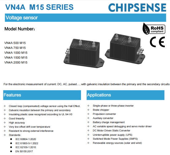
However, selecting a product based solely on its "maximum measurable voltage" is insufficient. First, the appropriate model must be determined by considering the busbar's normal operating voltage and its expected fluctuations. Second, it is essential to verify that the sensor's output format is compatible with the controller's data acquisition interface. Furthermore, factors such as measurement accuracy, dynamic response, insulation requirements, power supply conditions, and available installation space must also be evaluated. CHIPSENSE VN4A M15 voltage sensor offers a very wide measurement range and a broad selection of options.
It is particularly important to distinguish between the rated measurement voltage, the maximum measurement range, and the system's allowable continuous operating voltage. These parameters have different meanings, therefore, one cannot conclude that a sensor is suitable for a specific busbar voltage based solely on its maximum measurement range.For high-voltage traction and the emerging HVDC/SST application fields, the rated range, dynamic response, and isolation must be matched to the actual system conditions.
For closed-loop Hall-effect voltage sensors, the downstream data acquisition circuitry must be designed by taking into account the specific model's conversion ratio and recommended load, ensuring that the sensor's output can be accurately read by the control system. Additionally, the range of the sensor's output signal must align with the input specifications of the downstream circuitry. CHIPSENSE not only offers a wide range of measurement scales for customers to choose from, but also provides customized product solutions.
Likewise, the application areas and relevant standards listed in product documentation of CHIPSENSE do not imply that a specific vehicle model has already completed validation or received full-vehicle application approval. When integrating components into a vehicle system, it is still necessary to conduct component selection, design reviews, and validation in accordance with the vehicle’s technical requirements. CHIPSENSE provides comprehensive services to its clients.
Conclusion
Metro braking systems involve more than just slowing down a train, they encompass the conversion between mechanical and electrical energy, the utilization of regenerated energy, and the dynamic control of DC-side voltage.
Braking resistors address the dissipation of excess electrical energy, while braking choppers regulate resistive braking based on specific control strategies. Meanwhile, reliable DC-bus voltage measurement provides the essential foundation for both control and protection functions. CHIPSENSE current and voltage sensors are the result of an ongoing commitment to providing suitable solutions for an ever-growing number of customers.
For traction systems, the priority is not merely to pursue superior individual sensor specifications, but rather to ensure that the measurement range, dynamic response, isolation performance, and downstream interfaces are well-matched to the actual operating conditions. Component selection only carries engineering significance when the measurement stage is evaluated within the context of the entire control system.This is precisely the application-oriented philosophy behind CHIPSENSE current sensor and voltage-sensing products.
CHIPSENSEis a national high-tech enterprise that focuses on the research and development, production, and application of high-end current and voltage sensors, as well as forward research on sensor chips and cutting-edge sensor technologies. CHIPSENSEis committed to providing customers with independently developed sensors, as well as diversified customized products and solutions.
“CHIPSENSE, sensing a better world!”
www.chipsense.net