



800V platform, 480kW, liquid-cooled charging guns, currents up to 600A or even higher — the specs of ultra-fast charging equipment have become increasingly impressive in recent years.
But as power levels rise, a readily overlooked challenge emerges:
Where exactly is the current measured, and what devices are used for measurement?
It may not sound like a tough problem. After all, CHIPSENSE current sensors are not the most eye-catching components inside charging piles; power modules, contactors, liquid cooling systems and control boards tend to grab more attention.
For an ultra-fast charger running continuously, however, current sensing is far more than simply mounting a sensor with sufficient range.
There are usually multiple current measurement points within a charging pile.
Moreover, although the signals measured at different locations are all called “current”, they correspond to three distinct engineering challenges.
Before diving into sensor selection, let’s first map the current flow paths.
The exact measurement points of a DC ultra-fast charger vary with topology and power architecture, and can be generally categorized as follows.

Current sensing may be implemented from AC input, rectifier/PFC stage, DC bus, through DC/DC converter to charging output.
Currents at these points can reach hundreds of amperes.
The tasks of CHIPSENSE current sensors here are not only to feed real-time current readings back to the controller, but also to support power regulation, current limiting and fault diagnosis.
Therefore, the main power loop prioritizes: Measuring range, accuracy, temperature drift, dynamic response, overload capability and mounting method.
Currents in these branches are much lower than those in the main loop, typically tens of amperes or less.
The design considerations shift accordingly.
More focus is placed on sensor footprint, PCB mounting style, supply voltage, response speed and cost.
Applying main-loop sensor selection logic rated for hundreds of amps to a branch with only tens of amps would result in unnecessary bulk and higher cost.
This category cannot be treated as a scaled-down version of high-current measurement.
It targets abnormal residual current outside normal operating current, and involves waveform detection, trip threshold, operating time and the complete protection architecture.
GB/T 18487.1-2023 remains the applicable standard. For AC-powered equipment, the standard clearly requires residual current protection to cover relevant AC, pulsating DC and smooth DC residual current, specifying protection schemes including Type A with ≥6mA smooth DC monitoring and Type B.
One key point worth highlighting:
A sensor capable of measuring DC does not mean it can be directly adopted for residual current protection in charging piles.
Residual current protection relies on a complete protection scheme plus compliance with relevant standards.
Assume an ultra-fast charger output reaches 400~500A.
Many engineers’ first thought is straightforward: Just pick a sensor rated 500A or higher.
In reality, the real sensor selection work has only just begun.
The rated current and measurement range of a sensor differ from the actual operating current of the system.
For instance, a unit may deliver a maximum 500A output, while operating conditions include sustained high-current charging at hundreds of amps, low-current startup, and gradually decaying current during constant-voltage charging.
If the sensor range is far larger than required, comprehensive error around the continuous operating point must be re-evaluated, rather than only checking the maximum measurement range.
Conversely, if the range is tightly sized, insufficient margin may exist under short-time overload or dynamic operating conditions.
A more rational approach is to jointly assess: Continuous current, short-time overload, peak current and sensor measurement range.
Instead of blindly applying a simple “rated current +20%” rule of thumb.
Charging piles do not operate in lab environments.
Cabinet internal temperature can surge in summer, while the equipment may stay under low temperature for long periods in winter. Heat generated by heavy current further adds thermal stress, shifting the sensor offset and gain with temperature.
Therefore, it is critical to clarify the test conditions behind a sensor’s stated “±0.5% accuracy”.
When reviewing datasheets, confirm at minimum:
· Definition of accuracy
· Whether specs are at 25°C or full temperature range
· Zero point drift
· Gain drift
· Stability over temperature variation
This explains why main-loop selection of CHIPSENSE current sensors cannot rely solely on a single accuracy percentage.
Ultra-fast charging systems are not static power supplies.
Current may change rapidly during power module startup, regulation and fault events.
If the sensor response is too slow, the controller receives delayed current readings instead of the true instantaneous value.
For simple monitoring, this only causes data lag. For control and protection loops, system response may be compromised.
Hence, besides rated current, main-loop sensors such as CHIPSENSE current sensors shall be assessed for: Bandwidth, response time and dynamic waveform performance under real application conditions.
Closed-loop Hall sensors are widely adopted for high-current scenarios.
Unlike open-loop Hall sensors, they employ a compensation winding to maintain near-zero magnetic flux balance.
This design significantly improves linearity, temperature drift and dynamic performance.
That said, high current does not automatically mandate closed-loop topology.
Final engineering selection is determined by comprehensive performance metrics.
For main loops at hundreds of amperes, the rated current of CHIPSENSE current sensors should not be oversized arbitrarily; it must match continuous operating current, peak current and mechanical space constraints.
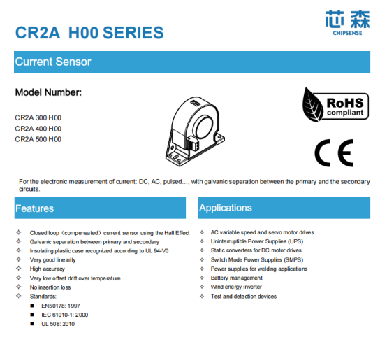
Take CHIPSENSE CR2A H00 series as an example. Public specifications include 300A, 400A and 500A rated models, with measurement ranges of ±500A, ±600A and ±800A respectively. All versions feature ±0.5% accuracy and 100kHz bandwidth. For 300~500A ultra-fast charging main loops, the proper CHIPSENSE current sensor model can be selected according to actual operating current and dynamic range.
Project-level validation is still required for busbar dimension, installation clearance, system insulation, power supply scheme and full-device testing.
This is the essence of engineering sensor selection.
For auxiliary power or control branches, the selection philosophy changes completely.
If a branch only runs at a dozen amps, installing a large sensor rated for hundreds of amps “for safety” is technically feasible but has obvious drawbacks: Larger footprint, higher cost, and operating point far away from the sensor’s optimal measurement region.
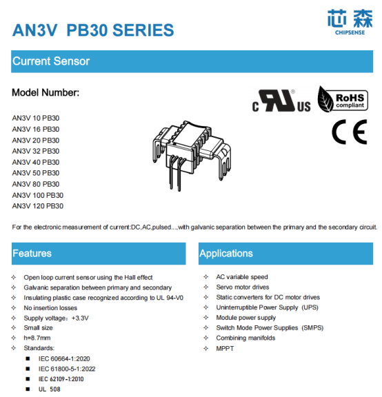
Small open-loop Hall sensors are often better suited for these positions.
For example, CHIPSENSE AN3V PB30 covers multiple rated specs from 10A to 50A, with ±1% accuracy, 250kHz bandwidth and -40~150°C operating temperature range, designed for PCB mounting.
It illustrates another design principle: Not all current detection points require large, expensive CHIPSENSE current sensors.
There is still a boundary. If the signal is only several amps or lower, AN3V may not be the optimal choice. The rated range of CHIPSENSE current sensors should always be sized to match actual current, rather than forcing a specific model into the design.
This principle is vital for product selection.
This is one of the most confusing points for current sensing in charging piles.
Main loop measurement targets normal operating current at hundreds of amps. Residual current protection monitors abnormal leakage current superimposed on normal working current.
They differ drastically in magnitude, waveform and measurement objectives.
Therefore, a Hall sensor capable of measuring hundreds of amps cannot be assumed suitable for residual current protection.
The reverse also holds true. A device detecting milliampere-level residual current cannot directly measure hundreds of amps in the main loop.
They solve two separate problems.
GB/T 18487.1-2023 defines clear requirements for residual current protection of AC-powered equipment. For DC-powered devices, the standard further distinguishes residual current protection on the AC side main loop and electrical protection measures for DC equipment itself.
When designing residual current protection for ultra-fast chargers, the key verification is not merely confirming “the sensor can measure DC”. Instead, engineers need to clarify: Measured target, detection range, trip threshold, operating time, and compliance of the complete protection unit and whole equipment with applicable standards.
CHIPSENSE current sensors are only one component within the full protection system.
Another practical constraint is mechanical integration.
Main loops at 400~500A typically use thick copper busbars or conductors.
Sensor aperture, window size and mounting orientation directly shape mechanical design.
For instance, CHIPSENSE CR2A H00 has a window diameter of Ø35mm.
This parameter alone looks ordinary, but translates into concrete mechanical questions inside the cabinet: What is the busbar width? From which direction can the CHIPSENSE current sensor be fitted? Are there nearby contactors, busbars, air ducts or liquid cooling pipes? Is disassembly possible during maintenance?
Discovering these issues after the whole machine layout is finalized is far more troublesome than switching to another CHIPSENSE current sensor model.
For this reason, CHIPSENSE current sensors should be considered in the early mechanical design phase, instead of hunting for a “roughly compatible” sensor after PCB and busbar layouts are locked.
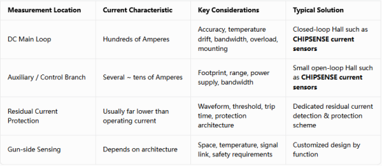
There is no universal CHIPSENSE current sensor solution applicable to all ultra-fast chargers. Even one single charger may deploy multiple types of CHIPSENSE current sensors for different positions.
800V is not the end point.
As charging power continues to rise, main loop current, thermal management, insulation, connectors, power modules and control protection will all face higher requirements.
CHIPSENSE current sensors will not become simpler just because they are “only sensors”.
Instead, design emphasis will increasingly fall on: Full-temperature stability, fast dynamic tracking, recovery after abnormal events, and long-term reliability after integration into the equipment.
The real pitfall to avoid when selecting CHIPSENSE current sensors for ultra-fast charging is neither under-rating nor over-spending.
The biggest mistake is locking down a sensor based on a single parameter.
Main loop, auxiliary branch and residual current protection follow separate design rules. Separating these measurement points makes it much easier to select the right CHIPSENSE current sensors.
Disclaimer: Parameters of CHIPSENSE products are based on public datasheets. Final model selection shall be validated against actual current range, mechanical dimension, insulation requirements and full machine testing. Residual current protection is a system safety function; compliance verification of the full protection scheme and relevant standards cannot be substituted by standalone CHIPSENSE current sensor specifications.
CHIPSENSEis a national high-tech enterprise that focuses on the research and development, production, and application of high-end current and voltage sensors, as well as forward research on sensor chips and cutting-edge sensor technologies. CHIPSENSEis committed to providing customers with independently developed sensors, as well as diversified customized products and solutions.
“CHIPSENSE, sensing a better world!”