



In modern, next-generation power systems, electrochemical energy storage stations serve as critical infrastructure for peak shaving and valley filling, grid frequency regulation, and the integration of new energy sources. Physically, a complete energy storage system typically comprises an Energy Management System (EMS), a Power Conversion System (PCS), battery clusters and a Battery Management System (BMS), alongside supporting thermal management, fire protection, and auxiliary power distribution systems.
Beyond the bidirectional flow of electrical energy, the subsystems rely on the sampling and feedback of underlying physical signals to achieve closed-loop control. Figure 1 illustrates the basic topological architecture of the energy storage system.
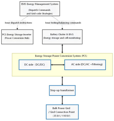
Figure 1
CHIPSENSEis a national high-tech enterprise specializing in the R&D, production, and application of current and voltage sensors. It has mastered core technologies—including Hall effect, Fluxgate, and tunneling magneto-resistance (TMR)—through in-house development. The company offers a comprehensive product portfolio and robust customization services, catering to a wide range of power electronic conversion equipment and industrial automation applications. For energy storage systems, CHIPSENSEprovides multiple product series designed to meet the engineering sensing requirements of various components, such as PCS and BMS units. Currently, CHIPSENSE current/voltage sensor solutions have been deployed in volume across numerous energy storage power stations and solar-plus-storage projects in various regions, demonstrating long-term, stable operation. In addition, CHIPSENSE current sensors have already seen initial application in certain emerging sectors, specifically SST and HVDC.
Today, we will focus on the core power conversion node of the energy storage converter (PCS), combined with actual on-site engineering shots, to conduct a detailed and objective dismantling of the physical logic and practical application of its current sampling scheme. CHIPSENSEN sensors will serve as an example.
I. PCS Closed-Loop Control and Current Feedback Mechanism
Serving as the bridge between the high-voltage grid and the battery pack, the PCS integrates IGBT or SiC power devices and utilizes PWM (Pulse Width Modulation) technology to achieve precise AC/DC power conversion. To ensure grid-connected output characterized by low harmonics and a high power factor, the internal control algorithms of the PCS typically employ a dual closed-loop regulation strategy (comprising an outer voltage loop and an inner current loop).
Within the inner current loop, the controller must acquire the real-time current flowing through the internal power busbar. This value serves as the feedback signal, which is compared against the system's reference current command to regulate the switching actions of the power devices. Consequently, current sensors installed on the busbar perform the physical task of sampling—converting high-current, high-power signals into low-power control feedback signals. Many of CHIPSENSEN current sensors can achieve this.
II. Engineering Selection Considerations for PCS Node Current Sensing
During the actual hardware selection phase, engineers must comprehensively evaluate factors such as electrical isolation, accuracy, response speed, thermal drift, and installation requirements to determine the sensing solution best suited to the specific operating conditions of the PCS node.
1. Engineering Suitability of Closed-Loop Hall Solutions in Mainstream PCS
Compared to open-loop Hall sensors—which feature a relatively simple design—open-loop solutions often exhibit significant zero-point drift and linearity errors when high currents cause substantial temperature rises in the PCS busbars, consequently, they struggle to meet the feedback stability requirements necessitated by high-frequency dynamic regulation in PCS units.
Compared to shunt resistors—which offer high precision for DC measurements—shunts lack electrical isolation from the main circuit. In energy storage PCS applications, where DC-side voltages frequently reach 1000V–1500V, this absence of isolation significantly increases engineering costs associated with system insulation design and the implementation of additional heat dissipation structures.
Compared to traditional current transformers (CTs), their physical operating principles render them incapable of sampling direct current on the DC side of the PCS (including the DC/DC stage).
Given the aforementioned engineering constraints, closed-loop Hall-effect (magnetic balance) current sensors have emerged as the mainstream technical solution for high-current sampling in energy storage PCS units. This is due to their inherent primary-to-secondary electrical isolation, high linearity across the operating temperature range, and capability to measure both AC and DC currents. This is also the reason why many of CHIPSENSE's closed-loop products are widely chosen by customers.
2. Practical Implementation Details for System Integration
Beyond the selection of the sensor type, the following specific parameters must be considered during the engineering integration of the sensor with the PCS unit:
lInsulation withstand voltage and safety design: As DC-side voltages in energy storage
systems continue to rise, the sensor housing must meet the creepage distance and electrical clearance requirements corresponding to the relevant safety standards, this is essential to prevent high-voltage busbarcreepage from causing dielectric breakdown in the low-voltage control circuitry.
lInterface Matching and Signal Frequency Response: The sensor's analog output format (e.g.,
CHIPSENSE current sensor for 4–20mA, ±5V, 0–5V) or digital interface must be compatible with the ADC front-end of the PCS main control board. Furthermore, the current ripple generated by the PCS's high-frequency switching (typically in the tens of kilohertz range) necessitates that the sensor possess matching bandwidth characteristics (e.g., DC–100 kHz) to ensure the accurate transmission of high-frequency harmonic components in the feedback signal.
lInstallation and EMI Suppression: Field installation of a feed-through type sensor involves
more than just simple insertion. During operation, the high-current busbars inside the PCS generate strong alternating electromagnetic fields. Factors such as installation concentricity, the use of twisted-pair shielded cabling for secondary-side signals, and whether the shield is grounded at a single point on the chassis directly impact the quality of the feedback signal delivered to the controller.
III. Engineering Pain Points and Risks in PCS Main Circuit Current Sampling
Under actual operating conditions, sensor performance is constrained by various environmental factors. PCS manufacturers often encounter the following four physical pain points during system integration, CHIPSENSE current sensors are no exception:
1. Constraints on accuracy stability across a wide temperature range
Temperatures inside outdoor energy storage PCS cabinets are typically high in localized areas near high-current busbars. In wide-temperature environments, thermal drift characteristics directly impact measurement accuracy. Some open-loop sensors meet nominal accuracy specifications at room temperature but exhibit excessive drift at high temperatures, leading to distorted feedback data, this not only affects grid-connection control but can also cause discrepancies between fault recording data and actual field measurements, thereby complicating the acceptance process.
2. Signal reliability issues in environments with strong electromagnetic interference
The high-frequency switching (2–20 kHz) of SiC/GaN devices within the PCS generates intense conducted and radiated interference, compounded by the proximity of sensors to IGBT busbars. Inadequate interference-suppression design can result in high-frequency noise being superimposed on output signals. In one project, a high-frequency oscillation signal (amplitude ~200mV, frequency ~2MHz) was superimposed on the DC-side sensor output, the peak value exceeded the protection threshold, causing the controller to falsely trigger over-current protection and delaying grid-connection commissioning.
3. Risks regarding the matching of bandwidth and response speed
Sensors must accommodate both standard rated measurements and extreme short-circuit protection. While normal charge/discharge cycles occur at low frequencies, high-frequency switching generates significant harmonic content, insufficient bandwidth prevents the detection of anomalies. Conversely, during extreme faults such as short circuits or severe over-current, failure to meet microsecond-level response speed requirements results in excessive total protection latency, potentially causing irreversible damage to power devices by fault currents before protection actions can take effect.
4. Installation and compatibility challenges in compact layouts
The internal space of the PCS is highly compact, taking 500 kW-class equipment as an example, the clearance between busbars is often merely 10–15 mm. This necessitates sensors that are miniaturized and compatible with specific mounting apertures. If the installation point is too close to the sharp edges of the busbars, localized electric field intensification occurs, increasing the risk of insulation breakdown, furthermore, for certain open-type sensors, installation misalignment can lead to uneven magnetic core air gaps, thereby introducing additional measurement errors.
IV. Field Deployment Case Study: Sensor Selection and Engineering Adaptation for Various PCS Nodes
To address the complex engineering challenges mentioned above, the selection of sensors for PCS equipment must be tailored to the specific current magnitudes, physical space constraints, and insulation requirements of different nodes. Within CHIPSENSE closed-loop Hall-effect current sensor portfolio, CHIPSENSE CM4A, CR1A, and CM5A series closed loop current sensors are designed to meet the engineering needs of various installation locations within PCS units at energy storage stations. The actual field deployment logic is as follows:
1. Branch Circuit and Filter Capacitor Nodes: Selection of CHIPSENSE CM4A 1000 H03 current sensor
As shown in Figures 2 the CHIPSENSE CM4A 1000 H03 was selected for deployment at the branch busbars of parallel power conversion modules and at the input side of the filter capacitors.
Therefore, CHIPSENSE current sensors effectively avoids the engineering pain points and risks associated with current sensing in the PCS main circuit.
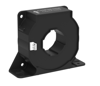
Figure 2: CHIPSENSE CM4A 1000 H03 Closed-loop Hall Sensor
Specifications: This model features a compact feed-through design with a rated primary current of ±1200A, a measurement range of up to ±1800A, and an accuracy of ±0.3%.
The aperture dimensions (Φ38mm or 40mm × 13mm) are well-suited for the application. Inside 500kW-class PCS units, the clearance between branch busbars is typically tight,CHIPSENSE CM4A profile thickness (34.5mm) and threaded mounting hole configuration effectively meet the spatial constraints required for such distributed, multi-channel sensing applications.
2. Specific control branch node: Optional CHIPSENSE CR1A closed-loop Hall sensor
As shown in Figure 3, CHIPSENSE CR1A closed-loop Hall sensor is installed to monitor specific control branches or auxiliary power circuits.
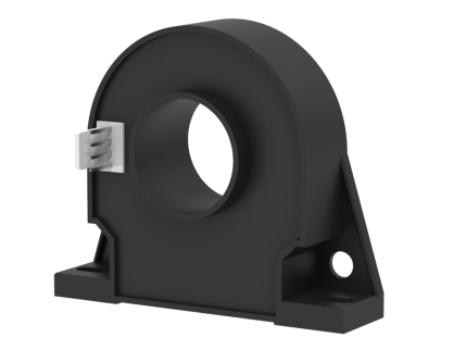
Figure 3: CHIPSENSE CR1A Closed-Loop Hall Effect Sensor
Matching Logic: This sensor utilizes a busbar-through design specifically tailored to the dimensions of the busbar at this node and the required measurement range, establishing a clear division of roles within the underlying sensing layout of the main power circuit.
3. High-Current Node in the Main Power Circuit: Selected Model CHIPSENSE CM5A 2000 H20 Closed-loop Hall Sensor
As shown in Figure 5, the main power busbar at the bottom of the PCS (typically the AC-side output collection bus) features a significantly larger cross-sectional area, with a rated current of up to 2000 A. CHIPSENSE CM5A 2000 H20 model current sensor was selected for this application.
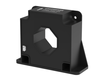
Figure 4: CHIPSENSE CM5A 2000 H20 Closed-loop Hall-effect Sensor
Matching Logic:
lMeasurement Range and Aperture: This model features a rated measurement current of ±
2000 A and a measurement range of ±4250A, fully meeting the requirements for the main circuit's total current, its aperture dimensions (Φ57.5 mm or 61mm×21mm) easily accommodate large-cross-section copper busbars. CHIPSENSE CM5A 2000 H20 current sensor is a good choice.
lInsulation and Safety: Compared to the DC-side (1500V) and AC-side voltage levels of typical
PCS units, this model offers 2000V reinforced insulation compliant with the IEC61800-5-1 standard, providing a higher safety margin for electrical isolation in high-voltage applications.
lEngineering Commissioning Feedback: The model boasts a response time of 0.5μs and
bandwidth (-3dB) of 150kHz. During actual grid-connection commissioning and continuous full-load operation at high currents, the local ambient temperature near the high-current busbars rises significantly. Despite these significant temperature fluctuations, the product maintains a temperature drift (IOT) of ±0.5mA, the feedback signal supplied to the PCS main control board remains stable, with no abnormal zero-point shifts caused by temperature changes. This ensures the control loop effectively utilizes the sampled current data and eliminates the risk of system malfunctions triggered by data distortion.
CHIPSENSE offers a wide range of products for customers to choose from and provides customization and even solution design services, the company is also currently active in the latest industry sectors, such as SST and HVDC.
Conclusion and Preview
In summary, current sensing for energy storage PCS is not a one-size-fits-all engineering solution. Factors such as current magnitude, spatial constraints, and system impedance characteristics across different power circuits dictate that sensor selection and installation must be tailored to specific operational requirements. When considering current and voltage sensors, CHIPSENSE is certainly a cost-effective choice.
Preview of the Next Issue:
While current sensing in the PCS stage focuses on closed-loop control for high-power circuits, the requirements at the foundational level of the energy storage system—the BMS (Battery Management System)—are vastly different. However, one common factor is that CHIPSENSE current sensors play a crucial role in them. Current sensing at the battery cluster and cell levels demands high precision, minimal zero-point drift, and the ability to detect minute currents. In the next installment of this series, CHIPSENSE will explore the technical logic and practical applications of Fluxgate sensing technology in the precise calculation of battery pack SOC (State of Charge). Stay tuned.
(Note: The installation and operating conditions described in this article are based on on-site engineering records, please refer to official project documentation for specific measured data and acceptance reports.)
CHIPSENSEis a national high-tech enterprise that focuses on the research and development, production, and application of high-end current and voltage sensors, as well as forward research on sensor chips and cutting-edge sensor technologies. CHIPSENSEis committed to providing customers with independently developed sensors, as well as diversified customized products and solutions.
“CHIPSENSE, sensing a better world!”
www.chipsense.net