


Light is essentially an energy source. In nature, sunlight is a free and easily accessible energy source. When sunlight shines on the surface of a crystalline silicon cell or thin-film cell (Called a solar panel), the electrons start to flow under the drive of energy, and after connecting to the line, current will be generated, which converts solar energy into DC power and supplies power to the load at the back end. When the load does not need electricity or light load, the remaining energy can also be stored (charging the battery), and when there is no sunlight and electricity needs to be used at night, rain, etc., it is powered by the battery instead.
The block diagram of a complete, small-system photovoltaic solar device is as follows:
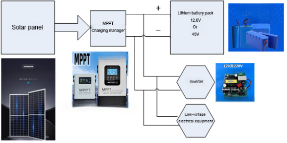
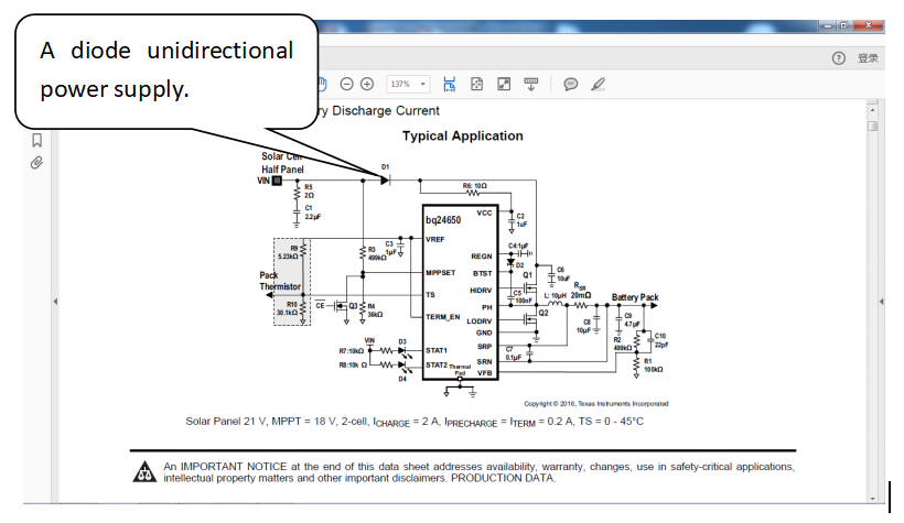
The electricity emitted by the solar panel is not a stable power source. Throughout the day, the position of the sun will continue to change, and the output power of the solar panel will vary with the intensity of the sun and the angle formed by the light and the solar panel. In this way, a controller called MPPT is required - tracking the maximum power. At present, the smallest system of photovoltaic equipment usually uses special ICs with simple peripheral circuits to achieve a complete application. The following is the circuit diagram of the MPPT application model BQ24650 provided by TI manufacturers:
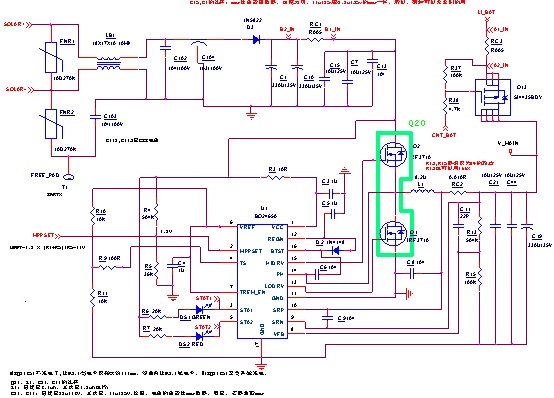
The following is a circuit diagram designed based on the recommended application circuit diagram of a manufacturer, retaining only the solar input and charging module. As shown in the figure, the function of diode D3 is to block the reverse discharge of the battery to the solar panel when there is no solar input.
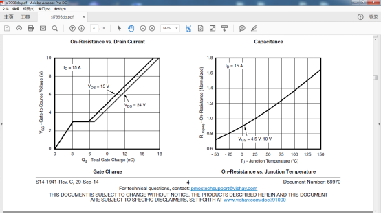
However, such unidirectional diode components can introduce significant energy losses: taking a solar panel with a nominal 55W as an example, the maximum measured output power is generally about 36W. When the MPPT operating point is set to 18V, under full power output conditions, the diode generates at least 0.7V * 2A = 1.4W (calculated according to the typical operating current 2A) power loss, which is dissipated in the form of heat energy, which constitutes an ineffective load on the system.
Most of the places that require the use of solar equipment are usually unattended places that cannot be covered by ordinary electricity. Such equipment usually needs to meet the working needs of timing and or emergency states, and must also have the ability to operate self-sustainably in long-term rainy weather. In order to facilitate human transportation, the volume of the equipment should be strictly controlled. Therefore, the higher the overall energy efficiency will be better. The design should minimize the ineffective energy consumption.
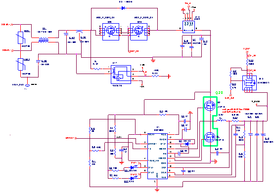
So how to optimize the application scheme? The following are two solutions for reference:
1.Use the voltage sensor device VN2A 25 P00 of CHIPSENSE, the range of the device is 10-1000V; cooperate with the relay (or other shutdown circuit), once the input voltage is detected to be lower than the MPPT voltage value, then disconnect the relay (or other shutdown circuit).
2. At the same time, using the CHIPSENSE voltage sensor VN2A 25 P00 and the Hall current sensor AN3V or AN4V A series are used at the same time; at the same time, if the solar voltage is less than 18V and the output current of the solar energy is less than 0.1A, it is considered that there is no sunlight, and the relay is disconnected. The two devices of VN2A 25 P00 and AN3V /AN4V A consume a total of about 30mA of current.
The above scheme also requires strict attention to the selection of power MOS transistors. To select a MOS transistor with appropriate parameters according to the output capacity of the MOS driver, let the MOS transistor open and close quickly to reduce the heat generation of the MOS itself.
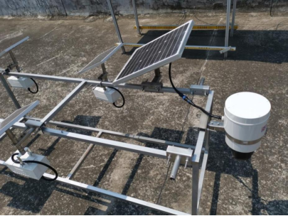
The picture below shows a complete set of equipment put into production after combining the above optimization design. The full set of equipment is equipped with a nominal 55W solar panel, a 12.6V/50Ah ternary lithium battery, and the total weight of the full set of equipment is about 11KG. A person can climb a 50-meter-high power tower and install it.
As long as there is sun, the MPPT charges the battery pack with a full load of current. During the test, this happened many times, from about 10 am to 3 pm, when the sun was at its peak, the MPPT charged the battery with a continuous current of at least 3A, and at this time, the internal temperature of the device only reached about 55℃.
The video camera works regularly every hour, first scanning 360 degrees, and then shooting several preset key areas. All images are sent back to the backstage through the 4G device; and the backstage is supported to control the camera at any time point. Continuous testing shows that the device supports up to 15 consecutive days of uninterrupted work in rainy. The product is being delivered to solar video surveillance systems in power towers, ports and shipping industries in batches.
Noted:
This article is original by CHIPSENSE. Without the written authorization of the copyright owner, no unit or individual may reprint, excerpt, or reproduce all or part of the content of this article in any form, nor may they engage in tampering, plagiarism, or other acts of copyright infringement. If found, legal responsibility will be investigated according to law.
CHIPSENSE is a national high-tech enterprise that focuses on the research and development, production, and application of high-end current and voltage sensors, as well as forward research on sensor chips and cutting-edge sensor technologies. CHIPSENSE is committed to providing customers with independently developed sensors, as well as diversified customized products and solutions.
“CHIPSENSE, sensing a better world!
www.chipsense.net