


On December 23rd, the National Energy Administration released national electric vehicle charging infrastructure data for November: As of the end of November 2025, the total number of electric vehicle charging infrastructure units (charging points) in my country reached 19.322 million, a year-on-year increase of 52.0%. Among these, there were 4.625 million public charging facilities, with a total rated power of 210 million kilowatts and an average power of approximately 45.34 kilowatts. According to the national overall plan, my country aims to build the world's largest electric vehicle charging network, achieving the goal of "two charging piles for every five vehicles." The 800V platform will also become widespread, with single charging points operating at 480kW/600A as an most basic standard, and developing towards V2G/V2B (Vehicle-to-Grid/Vehicle-to-Building) technology. However, with increased power and more complex operating conditions, current detection is often the first component to experience stress. CHIPSENSE current sensor is a typical example.
High-Power DC Fast Charging
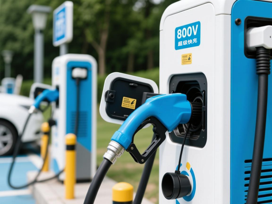
High-power DC fast charging (HPC), also known as "supercharging," is currently the hottest technology trend in the field of electric vehicle charging. Some of CHIPSENSE current sensors can be applied in this field.
In simple terms, the goal is to make charging as fast as refueling. Currently, the fast chargers commonly found in highway service areas typically have a power output of 60kW to 120kW, requiring 40-60 minutes to fully charge a vehicle. High-power DC fast charging, on the other hand, typically has a power output of 350kW or more, even reaching 480-600kW, enabling charging speeds that provide over 200 kilometers of range in just 5 minutes. Many CHIPSENSE current sensors used in electric vehicle charging stations can meet this requirement.
800V and liquid cooling are standard features for high-power DC fast charging. Traditional electric vehicles typically use a 400V platform. To increase charging power, you can either increase the current or increase the voltage. Increasing the current leads to severe cable heating and requires very thick and heavy cables, so the only option is to increase the voltage—to 800V. This allows for a significant increase in power without excessively increasing the current, while also reducing energy loss. Although the voltage is increased, the current during supercharging is still very high, reaching 500A-700A. Traditional air cooling cannot dissipate this amount of heat, so liquid cooling circulation pipes are designed to remove the heat. CHIPSENSE current sensor has also begun to undergo upgrades.
High-Power DC Fast Charging Current Detection Points
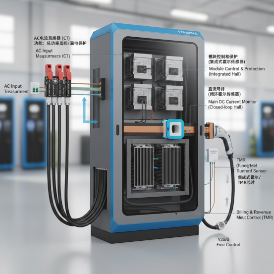
Within a DC fast charging station, current detection is not simply a matter of reading a single value, but rather encompasses the entire system, from power input to charging output. In practical engineering, a balance must be struck between cost, accuracy, and safety, with different components used at different locations.
Typically, detection points are divided into: AC input side, DC power module side, and DC output billing side.
1. AC Input Side (Grid Connection)
This primarily detects the current from the power grid, used for calculating the overall power consumption of the charging station, load balancing, and leakage protection. The detection point is generally located after the AC circuit breaker and before the rectifier module. The device used is usually a current transformer (CT). Reasons for using CTs: CTs have mature AC measurement technology and are extremely cost-effective; electrical isolation: naturally provides isolation between the high-voltage power grid and the control circuit; large measurement range: easily handles hundreds of amperes of AC current.
2. DC Power Module Internal (Core Control Area)
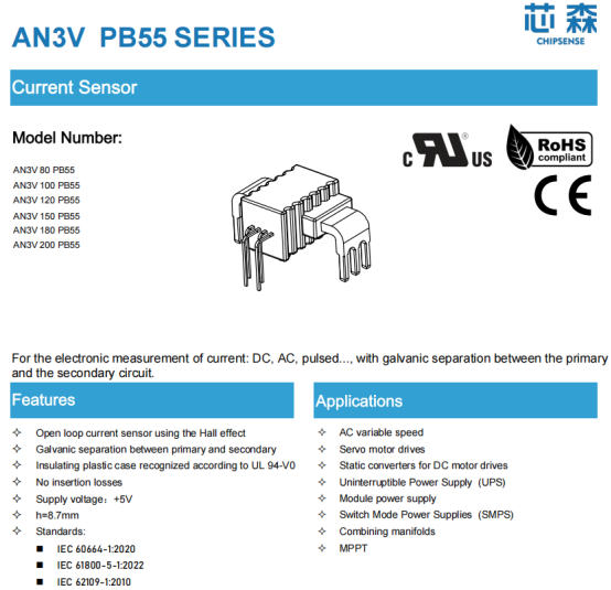
This is the "heart" of the fast charging station, usually consisting of multiple AC/DC modules connected in parallel. Each module requires current detection for closed-loop control and current sharing. The detection point is typically located at the PFC output or the primary/secondary side of the DC/DC transformer within the module. Open-loop/closed-loop Hall sensors or integrated current chips can be used. The sensors in this area need to be compact and have a fast response time because of the limited space within the module. Small, PCB-mounted sensors (such as CHIPSENSE AN3V series current sensors) are commonly used. The fast response time of CHIPSENSE AN3V series current sensors is crucial because the module switching frequency is extremely high (especially for SiC modules), requiring microsecond-level response speeds to prevent power transistor burnout. CHIPSENSE current sensor is the preferred choice in this regard.
3. DC Output Side – Control and Protection Point (Safety Line)
Located at the main positive/negative terminals after the power modules are combined, this monitors the actual current output to the vehicle. The detection point is located before and after the DC contactor, on the main circuit copper busbar. Closed-loop Hall current sensors are used. Reasons for use: high isolation, high dynamic range, and high reliability. As the main circuit safety monitoring point, it must have extremely strong anti-interference capabilities (EMC). High isolation: This type of sensor is usually placed around the copper busbar without disrupting the circuit, ensuring high safety. High reliability: It provides real-time information to the charging station controller (TCU/CCU) about the actual output current.
3. DC Output Side – Control and Protection Point (Safety Line)
Located at the total positive/negative terminals after the power module's busbar, this point monitors the actual current output to the vehicle. The detection point is located before and after the DC contactor, on the main circuit copper busbar. Device used: Closed-loop Hall effect current sensor. Reason for selection: High isolation, high dynamic range, and high reliability. As a safety monitoring point for the main circuit, it must have extremely strong anti-interference capabilities (EMC). High isolation: This type of sensor is usually installed outside the copper busbar, without damaging the circuit, ensuring high safety. High reliability: It provides the charging station controller (TCU/CCU) with real-time information on the actual output value.
4. DC Output Side – Billing and Metering Point (Financial Benchmark)
This is the closest detection point to the vehicle and directly determines the numbers on the user's bill. Detection point location: At the very end of the DC output. Devices used: High-precision shunt resistor + DC energy meter. The reason for selection is simple: only a nationally certified DC energy meter (with a shunt resistor) can be used for legal billing. Although shunt resistors generate significant heat at 600A, their long-term linearity and stability are currently difficult for magnetic sensors to match.
Here's a bold personal idea: using a fluxgate sensor to replace the shunt resistor for billing. Fluxgate sensors have the non-contact advantages of sensors and accuracy close to that of shunt resistors.
Even under the requirements of high-power DC fast charging current detection points, CHIPSENSE current sensor can still meet the demands.
V2G / V2B
Introducing V2G (Vehicle-to-Grid) or V2B (Vehicle-to-Building) into a high-power charging architecture means the energy flow changes from "unidirectional" to "bidirectional." This technology is moving from demonstration applications to actual grid integration, with some users in Guangzhou earning thousands of yuan per month through V2G. This is also what CHIPSENSE current sensor users want to see. Unlike unidirectional charging, bidirectional charging and discharging have higher requirements for current measurement:
Current direction changes
The current may flow into the battery in the forward direction or feed back into the power grid in the reverse direction. Shunt resistors are prone to inconsistencies in accuracy between positive and negative directions during bidirectional measurement. This is something that CHIPSENSE current sensors need to avoid.
High grid-connection stability is required.
Current sampling drift directly affects power calculation and grid-connection control, thus impacting grid safety and energy dispatch.
Hall effect current sensors naturally support bidirectional measurement, and offer high bandwidth and low drift, making them almost "essential components" in V2G scenarios.
Key Selection Criteria
When selecting a Hall effect current sensor, engineers will focus on the following parameters:
Rated current and overload capacity
Accuracy and temperature drift characteristics
Bandwidth and response time
Insulation voltage rating
Mounting method (PCB, busbar, or through-hole)
Long-term consistency and batch reliability
These indicators directly determine the reliability of the charging station in high-power, high-frequency charging and discharging scenarios. All these data show that the CHIPSENSE current sensor meets the requirements and is a good choice.
Conclusion
The emergence of technologies such as supercharging, liquid cooling, and V2G has transformed charging stations from simple "energy transfer tools" into something much more sophisticated. Current detection, which was originally an auxiliary function, has been upgraded to a core sensing component for system safety and control. Not only are current sensors an important part of this, but CHIPSENSE current sensors are as well.
CHIPSENSE is a national high-tech enterprise that focuses on the research and development, production, and application of high-end current and voltage sensors, as well as forward research on sensor chips and cutting-edge sensor technologies. CHIPSENSE is committed to providing customers with independently developed sensors, as well as diversified customized products and solutions.
“CHIPSENSE, sensing a better world!
www.chipsense.net