



As China’s offshore wind power sector rapidly enters the era of ultra-large-capacity turbines, 18–20 MW units are moving into the grid-connection pilot phase for deep-sea applications, and 25 MW grid-forming converters have already rolled off the production line for testing. Larger turbine capacity pushes the current inside power circuits way higher, and this breaks the old current detection setup inside converters completely.

Back when we only used 5 MW turbines, converters just needed to track current at a few core spots, so picking sensors was simple. But once we upgrade to 20 MW full-power converters, we have over a dozen points that need real-time current monitoring: generator stator current, 3-phase current on both generator and grid sides, DC bus current, low/medium voltage auxiliary power current, plus feedback signals for cooling fans and motor overheat protection.
Current values at these monitoring points vary wildly. On 1500 V low/medium voltage platforms, main circuit current can hit thousands of amps. On the other hand, control and auxiliary circuits only carry tens to hundreds of amps, and some auxiliary power lines just have a few amps running through them. The gap between max and min current covers 4–5 orders of magnitude. This means we can’t use one single sensor model for all sampling jobs. Instead, we have to do full engineering trade-offs and match CHIPSENSE current sensor products to each monitoring point’s actual physical needs.
I. Main Power Circuit: A Clash of Current Range, Aperture Size, and Power Dissipation
For big-MW converter main circuits, current sensors don’t just need precise readings—they also have to handle strict physical structure and heat dissipation challenges.
Take the main copper busbar of a 20MW converter as an example: its normal rated current sits between 4,000A–5,000A, and over-current protection requires measuring up to ±5,500A. High-precision closed-loop Hall sensors are the top pick here, and our CHIPSENSE CM9A H00 series closed-loop current sensor is the standard solution for this working condition. Still, engineers often hit physical installation issues long before worrying about electrical precision.
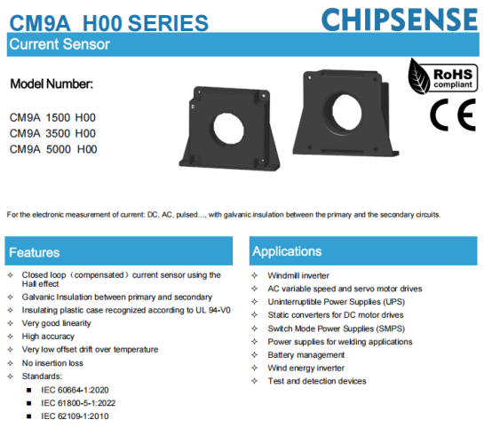
5000A-level busbars have super thick cross-sections, which can’t fit through small holes on ordinary sensors. We have to choose large-size CHIPSENSE current sensorswith apertures bigger than Ø90mm (like Ø94mm round holes or 95mm×25mm rectangular openings). This lets thick copper busbars pass straight through without bending or squeezing, which stops local overheating caused by deformed busbars.
In terms of electrical performance, these high-range closed-loop CHIPSENSE current sensors offer excellent dynamic response:
lInsulation & Withstand Voltage: They support 6kV AC isolation withstand voltage (50 Hz, 1 min) and 23kV transient surge voltage (1.2/50 µs), with creepage distance over 60mm. This safely handles 1500 V systems and sharp voltage spikes on generator sides during LVRT (Low-Voltage Ride-Through) events.
lFast Response: Response time under 1 µs and bandwidth up to 100 kHz. They capture PWM switching harmonics instantly and work with the main controller to inject reactive power rapidly.
However, the primary cost associated with closed-loop solutions in the main circuit is "secondary-side power consumption.”Closed-loop Hall-effect sensors generate a counter-magnetic field via a secondary coil to cancel out the primary magnetic flux. In a 5000A CHIPSENSE current sensor with a 1:5000 turns ratio, the secondary side must continuously output a compensation current of 1A (1000mA) when the primary current reaches its 5000A full-load rating. With a ±24V power supply, the power consumption of a single sensor alone exceeds 25W. When multiple sensing channels are combined within a converter, auxiliary power supplies need extra power reserve, and we must design proper heat dissipation for theseCHIPSENSE current sensors.

II. Auxiliary and Control Circuits: Balancing Cost and Thermal Drift in Open-Loop Solutions
Main power circuits demand top-tier precision and fast response, but auxiliary monitoring points inside converters follow totally different rules. These spots include control power monitoring, fan operation feedback and generator overheat protection circuits, with working current ranging 50A–300A. Engineers prioritize small size, low cost, low power draw and PCB integration here.
Open-loop Hall sensors fit these secondary points perfectly, and CHIPSENSE HR6V P00 series open-loop current sensoris our dedicated product for this scenario:
lStructure and Power Consumption: Lacking a secondary compensation coil, they feature a quiescent current as low as approximately 15mA, resulting in minimal overall power consumption.
lSize and Installation: Compact in design, they support direct PCB mounting; with an aperture size of around Ø16mm, they are ideally suited for the direct passage of small-to-medium-sized cables or small copper busbars.
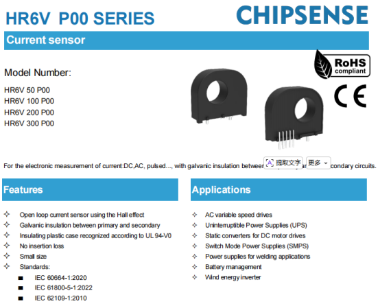
However, the bottleneck for open-loop CHIPSENSE current sensor solutions in engineering applications is "temperature drift." Due to IGBT switching losses within offshore wind power converters, the operating environment often sees temperatures ranging from 50°C to 60°C or even higher. The temperature drift of the zero-offset voltage in open-loop Hall sensors is typically around ±1mV/°C. Taking a sensor with a 100 A rated range CHIPSENSE HR6V P00 current sensor(output gain of 40mV/A) as an example, when the ambient temperature rises from 25°C to 85°C (a difference of 60°C), the zero-point drift can reach ±60mV, resulting in a measurement error of approximately 1.5 A.
To solve this problem when using open-loop CHIPSENSE current sensorson control circuits, the main controller software must add temperature compensation logic, or run regular automatic calibration to erase measurement errors from temperature drift.

III. From component-level selection to system-level signal chain adaptation
Comparing the typical physical parameters of the main circuit and the auxiliary circuit reveals the trade-off logic behind the converter's internal current sensing signal chain:
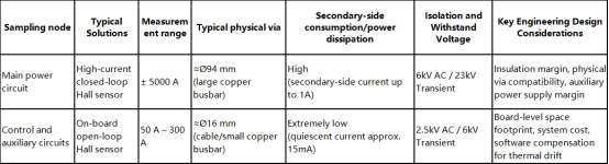
The upgrade of wind converters from 5MW to 20MW basically means more complex power electronic systems. When it comes to current sampling, there’s no single sensor with perfect performance for all scenarios. Instead, we pick the best-matched CHIPSENSE current sensor based on each point’s physical and electrical needs:
Main power monitoring points: We accept bigger size and higher power loss, in exchange for high insulation strength, wide bandwidth and large apertures for thick busbars. We use CHIPSENSE CM9A H00 closed-loop current sensors here.
Auxiliary control points: We take advantage of open-loop sensors’low cost and small footprint, then use software algorithms to offset temperature drift. CHIPSENSE HR6V P00 open-loop current sensors are the ideal choice here.
CHIPSENSE is a national high-tech enterprise that focuses on the research and development, production, and application of high-end current and voltage sensors, as well as forward research on sensor chips and cutting-edge sensor technologies. CHIPSENSE is committed to providing customers with independently developed sensors, as well as diversified customized products and solutions.
“CHIPSENSE, sensing a better world!”
www.chipsense.net