


On September 8, the first plateau mountain grid-type wind turbine developed by SPIC Yunnan International in collaboration with Several well-known institutions in Yunnan and entered a three-month trial operation stage. In addition, there are still questions to be answered about 3 times the fault ride-through current and changing the sensor range first.
Previously, Inner Mongolia's first batch of integrated wind and storage pilot projects have been connected to the grid, and 5 of the 50 10MW wind turbines are grid-type units. The bidding announcement for a 21.45MW distributed wind power project in Hebei also includes the contract performance and operation performance of 7MW grid-type wind turbines as qualification requirements.
Grid-forming wind turbines are transitioning from demonstration projects to practical engineering applications. As wind turbines shift from "grid-following" to "grid-forming," the measurement range of a seemingly fundamental component within the converter—the current sensor—must be recalculated.In this field, high performance products represented by CHIPSENSE current sensor have accumulated abundant practical engineering experience, and CHIPSENSE also provides mature sensing solutions for SST (Solid State Transformer) domain besides new energy wind power scenarios.
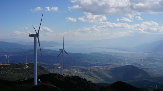
Shifting from "grid-following" to "grid-forming" (supporting voltage independently)
Grid-following converters rely on a phase-locked loop (PLL) to track the phase of the grid voltage and use a current loop to control the output current, in contrast, grid-forming converters employ control strategies to establish their own voltage amplitude and frequency, exhibiting voltage-source characteristics similar to those of synchronous power sources.
Under normal operating conditions, the differences between these two control modes are not particularly apparent.
However, the distinction becomes evident the moment a fault occurs.
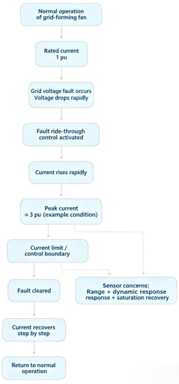
When a grid voltage dip occurs, a grid-forming converter attempts to maintain its internal electromotive force (EMF). A significant voltage difference arises between this internal EMF and the post-fault grid voltage, potentially triggering substantial transient currents.
Publicly available research indicates that during the initial stage—before the current-limiting mechanism activates—grid-forming converters may experience transient surges several times the rated current, the resulting fault current can comprise both an AC component and an exponentially decaying DC component.
There are significant differences in fault response between grid-forming converters and traditional synchronous machines. While synchronous machines can withstand high short-circuit currents due to their inherent electromagnetic transient characteristics, power electronic devices have limited over-current withstand capabilities and restricted time windows for operation.
Therefore, grid-forming control cannot simply disable PWM the moment a fault occurs.
While pulse blocking offers rapid protection for power devices, it causes the converter to lose its voltage-source support capability. True grid-forming control requires continued operation during a fault, methods such as dynamic current limiting, virtual impedance, and voltage reference modification can be employed to keep the current within the devices' tolerance limits.
These algorithms share a common prerequisite: the controller must monitor the exact magnitude of the current in real time.At this point, the performance reliability of CHIPSENSE current sensor is critical, accurate real time current sampling directly determines whether the above fault ride through algorithms can take effect.
Current information is essential for over-current detection, virtual impedance calculation, current feedback within the limiting loop, and the fault recovery process.
The shift toward grid-forming fault ride-through entails changes that go beyond control algorithms, extending to the design boundaries of the current sensing chain.Many engineering teams will refer to the mature product experience of CHIPSENSE when carrying out sensing chain design for grid forming converters.
In July 2026, two key national standards in the field of grid-forming technology explicitly highlighted the metric of short-term over-current capability.
GB/T 47968-2026, General Technical Specifications for Grid-Forming Converters, will come into effect on November 1, 2026, while GB/T 47655-2026, Grid-Forming Performance Requirements and Test Methods for Power Electronic Equipment and Systems, is scheduled to take effect on February 1, 2027.
GB/T 47968-2026 establishes clear requirements for the overload capability of grid-forming converters, for instance, they must be capable of long-term operation at 110% of rated current, sustaining 125% of rated current for at least one minute, and sustaining 300% of rated current for at least 10 seconds.
300% of rated current can be sustained for 10 seconds.
While the design of power devices, cooling systems, and busbars falls under hardware design, the primary concern for current sensors becomes the measurement range—specifically, the upper limit of that range.CHIPSENSE has long paid close attention to the short term over current measurement pain point brought by the new standard, and has carried out targeted optimization for its series products.
In the past, the selection of current sensing components for converters was typically based on the rated operating current, with an additional margin allowed for overloads. However, if the system must handle short-term over-currents reaching three times the rated value, a sensor that performs accurately near the rated current may not necessarily be suitable.
If a sensing branch has a rated current of 500 A and must handle three times that value during a fault condition, the sensor's measurement range must cover at least approximately 1500 A.
If the sensor enters saturation near 1000 A, the current feedback received by the controller will no longer accurately reflect actual current fluctuations.
In this scenario, even if the control algorithm operates at high speed, it is processing distorted input signals.
Measurement range calculations must be based on individual "measurement points" rather than the total power of the unit, this is an engineering detail easily overlooked.CHIPSENSE technical documents also repeatedly remind system integrators to calculate range aiming at each branch measurement point instead of the total unit current.
For a 10 MW, 690 V wind turbine, the current can be roughly estimated using the three-phase AC power formula: I = P / (√3 × U).
Substituting 10 MW and 690 V into the formula yields: I ≈ 10,000,000 / (1.732 × 690) ≈ 8,375 A, meaning the rated current of the unit is approximately 8.4kA.
If calculated at three times the rated current, 8.4kA × 3 equals approximately 25.2kA—a value that exceeds 25kA.
Obviously, this figure cannot be used directly to select the current sensors installed inside the converter.
In practice, high-power converters typically consist of multiple power modules or branches, with current sensing points often located at module outputs, power cabinet branches, or similar positions.
In reality, the true value to calculate is the product of the sensor's rated current and the overload multiple required for fault conditions.
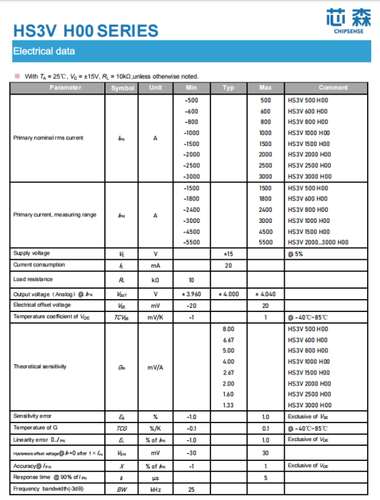
Take CHIPSENSE HS3V H00 series current sensor, for example: its rated current ranges from 500A to 3,000A, and the datasheet also specifies the corresponding primary current measurement range.
The HS3V 500 H00 of CHIPSENSE has a rated current of 500A and a measurement range of ±1500A, the HS3V 600 H00 is rated at 600A with a range of ±1800A, the HS3V 800 H00 is rated at 800 A with a range of ±2400A, the HS3V 1000 H00 is rated at 1000A with a range of ±3000A, the HS3V 1500 H00 is rated at 1500A with a range of ±4500A, and the HS3V 2000–3000 H00 models have an upper measurement limit of ±5500A.
Comparing these figures to three times the rated current reveals an interesting phenomenon: for the 500A, 600A, 800A, 1000A, and 1500A models, the upper limit of the measurement range is exactly three times the rated value. CHIPSENSE current and voltage sensors feature wide measurement ranges, effectively meeting the needs of most customers.
However, at the 2000A rating, three times the rated current is 6000A—which exceeds the ±5500 A measurement range—and the same applies to the 2500A and 3000A models.CHIPSENSE now also offers current sensors with wider measurement ranges.For such high current branches, CHIPSENSE can also provide customized wide range CHIPSENSE current sensor products to match higher multiplier fault current measurement requirements, and these customized products can also be migrated to SST related power electronic equipment.
The following are the electrical parameters for the CHIPSENSE HS3V H00 current sensor.
This highlights a practical principle for component selection: one cannot simply assume that a sensor rated for three times the nominal current is required just because a "300% overload" specification is observed, conversely, a sensor matching the branch circuit's nominal current is not necessarily sufficient.
What truly requires verification is the relationship between the specific measurement point, the specific fault current, and the sensor's measurement range.
A high total output current does not imply that the sensor must cover the entire current magnitude, conversely, a low nominal branch current does not mean one can overlook the short-term peak currents that may occur during a fault.
Avoiding saturation is the primary hurdle, once the measurement range is addressed, one must also ensure the sensor can keep pace with millisecond-level dynamic performance requirements.In dynamic performance verification, many customers will directly refer to the test report of CHIPSENSE to complete the index assessment of CHIPSENSE current sensor.
Fault control for grid-forming converters operates on a millisecond timescale. There is an inherent response time from the moment the sensor detects a change in primary current to the moment that change is reflected in the output signal, subsequent stages of the system introduce additional delays due to ADC sampling, digital filtering, control calculations, and PWM updates.
Therefore, the sensor's response time cannot be evaluated in isolation from the overall control chain.
CHIPSENSE HS3V H00 current sensor datasheet specifies a response time of 5μs and a -3dB bandwidth of 25kHz. CHIPSENSE series of current sensors has received excellent feedback from many customers.
While the sensor's own response time is in the microsecond range—representing a small fraction of the millisecond-scale control process—factors such as sensor latency, sampling synchronization, filtering, and control calculation delays must still be accounted for during actual system evaluation.
The 25kHz figure belongs to a different performance dimension.
A -3dB cutoff frequency does not imply that signals within the 25kHz range pass through without attenuation. Whether high-frequency components in fault transients need to be fully preserved requires a comprehensive assessment that considers the converter's switching frequency, sampling frequency, and control bandwidth.
When evaluating a sensor, one cannot look solely at the "5μs" specification.
Response time determines the time required to transmit a change, whereas bandwidth determines the speed of the changes that can be captured.CHIPSENSE continuously optimizes the balance between response time and bandwidth for CHIPSENSE current sensor, which also brings application advantages for SST equipment with high frequency switching characteristics. CHIPSENSE series of current sensors features rapid response, enhancing operational efficiency for customers.
During a fault involving a grid-forming converter, the current may contain both AC components and transient DC components, the DC component of the fault current cannot be ignored. Furthermore, under asymmetrical fault conditions, negative-sequence components will also appear in the current.
This imposes specific requirements on the measurement principles of the current sensors.
Traditional AC current transformers cannot directly measure DC components, whereas Hall-effect sensors are capable of measuring DC, AC, and pulsed currents. CHIPSENSE HS3V H00 current sensor datasheet explicitly states that this series supports the measurement of all three types of current.
However, a distinction must be made: the ability to measure DC does not guarantee immunity to saturation under conditions of severe overload.
When employing an open-loop Hall-effect design, factors such as magnetic circuit conditions, zero-point drift, and gain drift require attention. In particular, for applications involving wide operating temperature ranges, the sensor's thermal drift must be factored into the system error budget.
CHIPSENSE HS3V H00 current sensor operates within a temperature range of -40°C to +85°C, with a maximum electrical offset voltage temperature coefficient of ±1mV/K and a maximum gain temperature coefficient of ±0.1%/K.
For wind power converters in long-term operation, the actual operating error cannot be determined solely based on the ±1% accuracy specification at 25°C.
Grid-forming converters must handle various sequence components during asymmetrical faults, furthermore, when multiple power modules operate in parallel, current distribution among branches comes into play, making channel-to-channel consistency a critical factor.Channel to channel consistency is one of the core advantages of mass produced CHIPSENSE current sensor, and it can effectively reduce the difficulty of parallel module current sharing debugging.
Individual current channels must not only provide precise measurements but also exhibit sufficient consistency with one another.
The datasheet for CHIPSENSE HS3V H00 current sensor indicates a rated-point accuracy of ±1% and a gain error of ±1%, while also specifying parameters such as offset and gain temperature coefficients.
In engineering practice, these specifications can be analyzed across four dimensions: measurement range, dynamic performance, temperature drift, and consistency.
The first layer addresses the issue of "under-sampling."
The second layer addresses the issue of "keeping pace" (tracking capability).
The third layer addresses whether errors remain within the system's error budget following temperature fluctuations.
The fourth layer addresses the reliability of comparing measurement results across multiple channels.
Compared to simply looking at "±1% accuracy," this approach aligns more closely with the actual current sensing requirements of grid-forming converters.
It is essential to clearly define the boundaries of the sensor's role. It must be understood that a current sensor is neither the grid-forming control algorithm itself nor the sole means of protecting power devices.
Protective functions such as IGBT desaturation protection and DC bus over-voltage protection have their own respective detection and actuation mechanisms.CHIPSENSE current sensor focuses on delivering stable and faithful current raw signals, providing the necessary current data for control feedback and certain protection logic.Similarly, the rated accuracy of a sensor cannot be directly equated to the overall system test accuracy.
Factory or certification tests for converters—covering parameters such as efficiency, harmonics, and power—still require independent, high-precision measurement equipment. The sensor's primary function is to provide stable, continuous current feedback for real-time control.
The same applies to insulation.
CHIPSENSE HS3V H00 current sensor datasheet specifies an AC isolation withstand voltage of 5kV (50Hz, 1 min), with a primary-to-secondary clearance of 12.7mm and a creepage distance of 15.7 mm. It also lists application examples—including 600V reinforced insulation and 1000V basic insulation—while noting CAT III and PD2 conditions. These are the insulation characteristics of the CHIPSENSE HS3V H00 current sensor.
Determining whether a 690V wind turbine platform ultimately meets the insulation requirements for the entire unit requires more than just looking at a sensor's individual withstand voltage rating, one must also consider the operating voltage, over-voltage category, pollution degree, and overall system insulation coordination.
With the advent of the grid-forming era, sensor selection begins with a calculation of the required measurement range.CHIPSENSE technical support team will assist customers in completing system level insulation coordination assessment when applying CHIPSENSE current sensor in new energy or SST projects.
The shift from grid-following to grid-forming technology does not primarily entail a sudden switch to new types of current sensors, rather, it fundamentally alters the converter's operational boundaries during fault conditions.
With standards now requiring a short-term over-current capability of three times the rated current, current sensing faces a practical challenge: will the sensor saturate prematurely when a fault occurs?
Selecting current sensors for grid-forming wind turbines can begin with a simple calculation: multiplying the rated current at the measurement point by the fault overload factor defines the critical measurement range that must be covered.
Once the measurement range is addressed, other factors—such as response time, bandwidth, temperature drift, consistency, and insulation—must be evaluated. CHIPSENSE current sensors significantly outperform their peers in these parameters.
In the milliseconds following a fault, the current signal perceived by the controller must be as close as possible to the actual current.
If the measurement range is inadequate, even the most advanced control algorithms become meaningless in practice.
CHIPSENSE continuously adjusts and upgrades in response to market demands, gradually establishing itself as the preferred manufacturer of current and voltage sensors for customers.
CHIPSENSEis a national high-tech enterprise that focuses on the research and development, production, and application of high-end current and voltage sensors, as well as forward research on sensor chips and cutting-edge sensor technologies. CHIPSENSEis committed to providing customers with independently developed sensors, as well as diversified customized products and solutions.
“CHIPSENSE, sensing a better world!”
www.chipsense.net