


In fields such as industrial automation, new energy vehicles, smart grids, and photovoltaic inverters, the selection of the current sensor's measurement range (range) directly determines data monitoring accuracy, equipment operating safety, and long-term operating costs. Many users face a dilemma when selecting a sensor: choosing a small range risks overloading and burning out core components, while choosing a large range may lead to the inability to detect small current changes, resulting in data distortion, or even hindering project progress due to excessive costs. In this case, the CHIPSENSE current sensor would be an excellent choice. How can one scientifically select the measurement range to ensure accurate coverage of actual needs? This article will systematically analyze the methods for selecting the measurement range of current sensors from the perspectives of technical logic, key influencing factors, and selection steps. CHIPSENSE current sensor can be used as a reference.
I.How serious are the consequences of selecting the wrong measurement range?
Scenario 1: Insufficient Measurement Range, Equipment Overload and Failure
In a factory, the original current sensor of a frequency converter had a measurement range covering only 90% of the rated current. During motor startup, the peak current (three times the rated value) directly exceeded the sensor's range, leading to the breakdown of the Hall element's PN junction and the burning out of the signal conditioning chip. This not only rendered the sensor unusable but also caused the frequency converter to shut down due to signal interruption, resulting in production line downtime and losses. These are problems that CHIPSENSE current sensors want to avoid.
Scenario 2: Measurement range is too large, leading to "distorted and invalid" data
When a laboratory was conducting current testing of precision electronic equipment, they used a 100A range sensor to monitor small currents within 5A. Due to the excessively large range, the measurement resolution was insufficient, and the data fluctuation exceeded ±2%, far exceeding the±0.5% error range allowed by the experiment. This resulted in invalid experimental data and prolonged the research and development cycle. CHIPSENSE current sensors are not like that.
The key conflict is that the range and accuracy of current sensors are inversely proportional—the larger the range, the lower the resolution of the output signal corresponding to a unit current; if the range is too small, it is easily damaged by instantaneous peak currents due to overload. The core of sensor selection is to find a balance between "covering the required range" and "ensuring accuracy."
CHIPSENSE current sensors undergo rigorous testing to ensure their accuracy and measurement range.
II.Four Core Factors Influencing Measurement Range Selection
1. Current Characteristics of the Application Scenario
The operating state of the current directly determines the basic measurement range and requires precise matching according to the type:
• Static current (e.g., continuous battery discharge, operating current of lighting equipment): The measurement range must cover the maximum static current, with a 20%-30% safety margin to prevent overload due to current fluctuations. CHIPSENSE current sensors are designed to avoid this problem during the development phase.
• Dynamic current (e.g., motor starting, frequency conversion of inverters, short-circuit current): The instantaneous peak value needs to be considered. For conventional dynamic scenarios (such as fan starting), the recommended measurement range is 1.5-2 times the peak current; for extreme impact scenarios (such as short circuits), it should be 2-3 times the peak value to prevent instantaneous overload.
• Pulsating current (e.g., switching power supply, photovoltaic inverter output current): The measurement range must cover both the peak and trough values to prevent repeated fluctuations at the range boundaries, which can lead to sensor fatigue and accuracy degradation.
2. Cumulative Effects of Environmental Interference
Harsh environments can indirectly affect range suitability and should be avoided in advance:
• Temperature effects: High temperatures (>85°C) can lead to a decrease in Hall element sensitivity and magnetic core permeability, effectively reducing the "effective range." An additional 10%-15% margin should be reserved. Low temperatures (<-40°C) may cause circuit instability, also requiring increased range redundancy.
• Electromagnetic interference: Strong electromagnetic environments from industrial frequency converters and high-voltage equipment may introduce interference currents. Sensors with strong anti-interference capabilities (such as EMC Level 4) should be selected, or the measurement range should be appropriately increased to avoid interference-induced overload protection triggers.
• High-voltage scenarios: In high-voltage (>1kV) environments, insulation layer heating may affect sensor performance. An additional safety margin should be reserved in the measurement range, considering the required isolation voltage.
3. Implicit Thresholds of Accuracy Requirements
The accuracy of current sensors is usually specified as a "percentage of full scale (%FS)," and the accuracy requirement directly limits the upper limit of the measurement range:
• If small current changes need to be monitored (e.g., ±10mA accuracy testing in a laboratory), a small-range sensor should be selected to improve resolution. For example, to detect a current change of 0.1A, and the sensor accuracy is 0.1%FS, the range should be ≤100A; otherwise, small fluctuations cannot be captured. Therefore, the accuracy requirements for CHIPSENSE current sensors are very high.
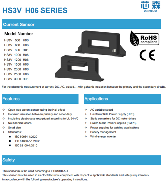
• For conventional industrial monitoring (e.g., ±0.5% error requirement), the requirements can be relaxed appropriately, and the range can cover the maximum current with some margin, without the need to excessively pursue a small range. CHIPSENSE adjusts the current sensor's range and accuracy according to requirements. CHIPSENSE HS3V H06 series current sensor can be used as a reference.
4. Considerations for Long-Term Stability
After prolonged use, the core components of the sensor will age, requiring provisions for stability:
• After aging, components such as Hall elements and magnetic cores may experience a decrease in linearity. It is recommended that the actual operating current does not exceed 70%-80% of the measurement range to avoid zero-point drift and reduced lifespan caused by prolonged operation at the upper limit of the range. CHIPSENSE current sensors have a longer lifespan than those of competing manufacturers.
• In scenarios involving frequent starts and stops or large current fluctuations (such as in new energy vehicle motor control), an additional 10% margin should be added to reduce component fatigue and wear. It's not just CHIPSENSE current sensors like this, other manufacturers also warn their customers to avoid this problem.
III.Scientifically Determine the Measurement Range to Accurately Cover Actual Needs
Step 1: Define Current Boundaries
Determine three key parameters through theoretical calculations, equipment manual consultation, or pre-testing:
• Regular operating current range (e.g., motor rated current 50A, operating range 30A-60A);
• Maximum dynamic peak current (e.g., starting peak 150A, short-circuit instantaneous peak 300A);
• Minimum monitoring current (e.g., equipment standby current 5A, which needs to be accurately captured).
All CHIPSENSE current sensor specifications are clearly stated in the datasheet.
Step 2: Evaluate Dynamic Characteristics
Calculate the "peak amplification factor" based on the current type:
• Static current scenarios (e.g., LED drivers): Use an amplification factor of 1.2-1.3 to cover normal fluctuations;
• Regular dynamic scenarios (e.g., fan, water pump startup): Use an amplification factor of 1.5-2.0 to handle startup peaks;
• Extreme impact scenarios (e.g., short circuits, sudden load changes): Use an amplification factor of 2.0-3.0 to withstand instantaneous overloads.
CHIPSENSE will also inform customers about these issues when they receive the current sensors.
Step 3: Reserve a Safety Margin
Add a 20%-50% safety margin on top of the "maximum dynamic peak current × amplification factor":
• General industrial scenarios: Total margin of 20%-30% (e.g., peak 100A × 1.5 amplification factor = 150A, select a range of 180A-200A);
• Harsh environments/critical equipment (e.g., new energy vehicle BMS, high-voltage power grid): Total margin of 30%-50% (e.g., peak 200A × 2.0 amplification factor = 400A, select a range of 520A-600A). CHIPSENSE will recommend current sensors with appropriate measurement ranges based on the customer's application.
Step 4: Verify Accuracy Matching
Based on accuracy requirements, determine the upper limit of the measurement range to avoid insufficient accuracy due to an excessively large range:
• Formula: Upper limit of measurement range ≤ (Minimum detectable current change) ÷ Sensor accuracy (%FS);
• Example: If a small current change of 0.5A needs to be detected, and the sensor accuracy is 0.2%FS, then the upper limit of the measurement range ≤ 0.5A ÷ 0.2% = 250A, ensuring that the measurement error for small currents is within the acceptable range. CHIPSENSE current sensors have always adhered to this requirement.
IV.Common Misconceptions and Pitfalls
Misconception 1: Blindly pursuing "large and comprehensive"
Large-range sensors are not only more expensive but also reduce resolution in the lower range. For example, using a 1000A range to monitor a 10A current may increase the error from ±0.5% to ±3%, completely failing to meet the requirements for accurate monitoring. CHIPSENSE current sensors have made significant efforts in this area.
Misconception 2: Neglecting current type compatibility
Failing to differentiate between DC, AC, and pulsating current characteristics, such as using a current transformer that only supports AC to measure DC current, or using a conventional Hall sensor for high-frequency pulsating current, leads to "false coverage" of the range, making it impossible to function properly. Many current sensor manufacturers tend to overlook this problem.
Misconception 3: Ignoring environmental and installation influences
Failing to increase the range margin in high-temperature and strong electromagnetic environments, or neglecting high-voltage isolation requirements during installation, can cause the sensor to overload due to environmental interference in actual working conditions, or lead to a decrease in accuracy that fails to meet the requirements. Therefore, CHIPSENSE current sensors incur high costs in terms of raw materials.
Misconception 4: Forgetting about long-term aging margin
Selecting the range only based on current needs without considering the range reduction after sensor aging can lead to the actual working current approaching the upper limit of the range after 1-2 years of use, resulting in decreased accuracy and frequent failures.This is a matter that not only other current sensor suppliers should pay attention to, but also CHIPSENSE.
Conclusion
The selection of the current sensor's measurement range is fundamentally a technical trade-off between "precise matching and appropriate redundancy," not simply "the larger the range, the safer" or "the smaller the range, the more accurate." Therefore, CHIPSENSE offers current sensors with different measurement ranges for various application fields. By following a four-step process—defining current boundaries, evaluating dynamic characteristics, reserving a safety margin, and verifying accuracy matching—and considering factors such as current type, environmental conditions, and long-term stability, it's possible to select a range that covers actual needs while ensuring both accuracy and safety. Proper selection not only extends sensor lifespan but also prevents cascading risks such as data distortion and equipment damage, providing reliable protection for stable system operation. When a customer submits a request, CHIPSENSE will help them select the most suitable current sensor.
Frequently Asked Questions (FAQ)
Q1: How to determine if a current sensor has insufficient range (overload)?
A: If the sensor output signal frequently reaches its upper limit, the zero-point drift continuously increases, or the appearance shows signs of packaging overheating or wire aging, it can be initially determined that the range is insufficient; testing with a standard current source will confirm this if the output does not change after exceeding the rated current range. A higher range product will then be needed.
Q2: How to determine the range for dynamic current scenarios (such as motor startup)?
A: First, obtain the peak starting current (usually 3-5 times the rated value) through the equipment manual or actual measurement. Select a range that is 1.5-2.0 times the peak current, and then reserve a 20%-30% safety margin to ensure coverage of instantaneous surges.
Q3: How to balance the range and accuracy of a current sensor?
A: Prioritize meeting accuracy requirements; for small current monitoring scenarios, choose a small-range sensor. If the current range is wide (e.g., 0-300A), you can choose a multi-range sensor or use a "main sensor + auxiliary sensor" hierarchical measurement scheme to balance coverage and accuracy. CHIPSENSE current sensor can achieve this.
Q4: How do high temperature and strong electromagnetic environments affect range selection?
A: High temperatures require an additional 10%-15% range redundancy to prevent insufficient "effective range" due to component sensitivity degradation; strong electromagnetic environments require the selection of sensors with high interference immunity, or appropriately increasing the range, to prevent interference signals from triggering overload protection.
Q5: Will the measurement range of the sensor change after long-term use?
A: Yes. After the Hall element and magnetic core age, the linearity and range will slightly decrease. It is recommended that the long-term operating current does not exceed 70%-80% of the range, and that regular calibration is performed. Adjust the usage strategy based on the calibration results to ensure that it always covers the actual needs.
Therefore, based on these issues, CHIPSENSE current sensors have been continuously upgraded, aiming to provide customers with cost-effective products.
CHIPSENSE is a national high-tech enterprise that focuses on the research and development, production, and application of high-end current and voltage sensors, as well as forward research on sensor chips and cutting-edge sensor technologies. CHIPSENSE is committed to providing customers with independently developed sensors, as well as diversified customized products and solutions.
“CHIPSENSE, sensing a better world!
www.chipsense.net