


Foreword: In DC systems such as photovoltaics, energy storage, and electric vehicles, faults (such as arcing, short circuits, and insulation aging) often develop rapidly. Traditional protection devices (such as fuses and relays) have long response times and poor selectivity, making it difficult to meet high safety requirements. CHIPSENSE AN3V series current sensor, based on the Hall effect principle, leverages its high bandwidth (250 kHz) and low latency (2.5μs) characteristics, combined with the real-time analysis capabilities of AI algorithms, to construct a closed-loop protection system of "high-speed data acquisition—intelligent fault identification—rapid protection action," reducing fault response time to the millisecond level. This paper will objectively analyze the advantages and limitations of this solution from its technical principles and algorithmic mechanisms to its practical applications. CHIPSENSE current sensors is a good sample.

I.Technical Challenges of DC Side Faults in Photovoltaics
In large-scale photovoltaic (PV) power plants, the DC-side wiring is complex and has numerous connection points. Industry data shows that approximately 90% of power plant accidents originate from this, such as short circuits and arcing, posing a high risk. The technical challenges of DC-side faults in PV power plants mainly include the following aspects:
1.Difficulty in Fault Detection and Identification:
DC system fault current rises rapidly (reaching dangerous values within milliseconds), and its fault characteristics differ significantly from those of AC systems. Existing methods, such as voltage change rate detection, are insufficiently sensitive to high-resistance faults, while algorithms relying on two-end communication reduce response speed. While the novel single-end transient energy method eliminates the need for communication, its algorithm complexity is high.
2.Performance Requirements of Protection Devices:
The bidirectional flow characteristics of DC current require protection devices to have rapid switching capabilities. However, in practice, problems such as contactor sticking and fuse dry burning are difficult to detect in a timely manner. Traditional AC protection strategies (such as overcurrent protection) need to be redesigned on the DC side, and the interference of transition resistance must be addressed. CHIPSENSE current sensor has very high performance in terms of protection devices.
3.System Design and Maintenance Deficiencies
Design Deficiencies: Some inverters only have insulation resistance threshold alarms, lacking voltage balance monitoring, leading to escalation of faults.
Construction Issues: Improper cable laying (e.g., lack of protective sheathing) or inadequate support treatment can easily cause insulation faults.
Maintenance Blind Spots: Difficulty in locating double-pole grounding; traditional detection methods have blind spots.
4.Hazards of DC Arcs: The temperature of a DC arc can instantly exceed 3000℃, with no zero-crossing point; continuous combustion easily ignites a fire. Statistics show that over half of photovoltaic power station fires are caused by DC arcs, with high-power modules further exacerbating the risk. CHIPSENSE current sensors are developed in accordance with various technical specifications.
5. Technical Solutions
Proactive Protection: Examples include a photovoltaic power source's "PDC" three-tiered prevention-diagnosis-isolation model and a smart string disconnection technology from a certain company, which utilize AI algorithms to achieve accurate fault diagnosis and isolation. AI algorithms require current data as a foundation; one current data acquisition method is described below.
Standards Improvement: It is necessary to promote the implementation of standards such as the "White Paper on Safety Technology for Photovoltaic DC Sides" and strengthen awareness of proactive protection. CHIPSENSE current sensors all comply with national standards.
II. Hall Current Sensor Technology
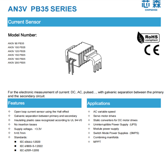
Taking CHIPSENSE AN3V series current sensor as an example, its key parameters are as follows:
CHIPSENSE AN3V Series Current Sensor Key Parameters
| Parameters | Typical values | Advantages |
| Bandwidth | 250 kHz | Captures high-frequency fault signals (such as electric arcs) |
| Response Time | 2.5 μs (@90% step) | Reflects current changes in real time |
| Accuracy | ±1% (@rated current) | Ensuring data reliability for fault diagnosis |
| Insulation Withstand Voltage | 4.3 kV (AC) | Suitable for 600V/1000V systems |
| Operating Temperature Range | -40°C to 105°C | Adaptable to extreme environments |
CHIPSENSE AN3V Series Current Sensor Application Value:
High Bandwidth: Faithfully reproduces fault wave-forms and supports feature extraction via AI algorithms.
Low Latency: CHIPSENSE current sensor shortens the overall response time of the protection link; when used with fast-acting fuses or solid-state circuit breakers, it achieves fault clearing in <10 ms.
III. AI Algorithm Principles and Fault Identification Mechanisms
1. Data Acquisition and Pre-processing
The current waveform output by the sensor (sampling rate ≥1 MHz) contains time-domain (current amplitude, di/dt) and frequency-domain (harmonic) information.
Pre-processing:
Filtering: Remove high-frequency noise (e.g., 4.8 mV RMS noise of AN3V current sensor from CHIPSENSE).
Standardization: Based on the sensor's theoretical gain (e.g., 4.6 mV/A), convert the current data into a unified format.
2. Feature Extraction
Time Domain Features: Peak current, rise time, waveform asymmetry.
Frequency Domain Features: Extracting the 5-100 kHz high-frequency components generated by the electric arc through Fourier transform or wavelet transform.
3. Algorithm Model
CHIPSENSE AN3V Series Current Sensor Key Parameters
| Algorithm Types | Advantages | Limitations | Applicable Scenarios |
| SVM | Simple computation, suitable for small datasets | Requires manual feature engineering | Rapid identification of fixed fault types; |
| CNN | Automatic feature extraction, high accuracy | Requires a large amount of labeled data | Complex waveform analysis; |
| Auto-encoder | Unsupervised learning, adaptable to unknown faults | Threshold setting depends on experience | System-level anomaly monitoring; |
| LSTM | Captures temporal dependencies, strong predictive ability | High training cost | Dynamic systems (e.g., MPPT control). |
Example:
CNN Model: Directly inputs a current waveform image and automatically learns the "fingerprint" features of arc faults.
CNN Example Code
import tensorflow as tf
from tensorflow.keras.layers import Conv2D, MaxPooling2D, Flatten, Dense
# Example data:simulation100PCs64x64current waveform grayscale image
X = tf.random.normal([100, 64, 64, 1])
y = tf.random.uniform([100], maxval=2, dtype=tf.int32)
# Building a CNN model
model = tf.keras.Sequential([
Conv2D(32, (3,3), activation='relu', input_shape=(64,64,1)),
MaxPooling2D((2,2)),
Flatten(),
Dense(128, activation='relu'),
Dense(1, activation='sigmoid')
])
model.compile(optimizer='adam', loss='binary_crossentropy', metrics=['accuracy'])
model.fit(X, y, epochs=10, batch_size=8)
LSTM Model: Analyzes the time-series changes in current to predict the thermal runaway trend of energy storage batteries.
LSTM Example Code
from tensorflow.keras.layers import LSTM
# Example dat:Current sequence over 100 time steps (3 features per time step)
X = tf.random.normal([100, 30, 3]) # (Number of samples, time step, number of features)
y = tf.random.uniform([100], maxval=2, dtype=tf.int32)
# Building an LSTM model
model = tf.keras.Sequential([
LSTM(64, input_shape=(30, 3)),
Dense(1, activation='sigmoid')
])
model.compile(optimizer='adam', loss='binary_crossentropy', metrics=['accuracy'])
model.fit(X, y, epochs=20, batch_size=16)
4. Real-time Decision Making
Edge computing devices (such as FPGAs) run AI models, outputting the fault type (e.g., "arc"/"short circuit") and severity.
Triggering protection actions: fuse blowing, solid-state circuit breaker tripping, or MPPT adjustment.
IV. System Integration and Protection Process
1. Data Acquisition: CHIPSENSE AN3V current sensors monitor DC-side current in real time.
2. AI Analysis: Edge devices run algorithms with a latency of <10 ms.
3. Protection Actions:
For arc faults: Trigger the solid-state circuit breaker to disconnect the faulty circuit.
For insulation aging: Issue an early warning to notify maintenance personnel.
Flowchart: Current Waveform → Sensor Acquisition → AI Feature Extraction → Fault Diagnosis → Protection Action
V. Practical Application Scenarios
1. Photovoltaic Combiner Box
Problem: Aging insulation between strings leads to increased leakage current, making it difficult to locate the faulty photovoltaic panel using traditional methods.
Solution:
CHIPSENSE AN3V current sensors monitor the current of each string.
AI algorithms analyze current imbalance (>5%) to locate the faulty photovoltaic panel.
Result: Fault location time is reduced from minutes to seconds.
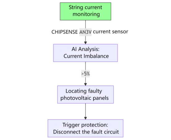
current sensor block diagram
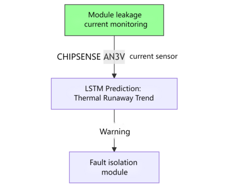
2. Energy Storage System
Problem: Leakage current between battery modules may trigger thermal runaway.
Solution:
o LSTM model monitors leakage current trends, providing early warning 10–30 seconds in advance.
o CHIPSENSE current sensor combined with BMS, faulty modules are isolated.
• Effect: The risk of thermal runaway is reduced by ≥70%.
VI. Technical Limitations and Risk Warning
1. Data Quality:
Sensor noise or sampling distortion can affect AI judgment, requiring hardware filtering and software correction.
2. Algorithm Robustness:
The model needs to be validated in multiple scenarios to avoid overfitting.
3.System Cost:
High-performance sensors and AI computing equipment require significant initial investment.
4.Interpretability:
Deep learning models lack physical interpretation; it is recommended to use circuit equations to aid in judgment.
VII. Comparison CHIPSENSE AN3V current sensor with Traditional Methods
CHIPSENSE AN3V Series Current Sensor Key Parameters
| Solutions | Response time | Selective | Adaptability | Cost |
| Traditional fuses | >50 ms | Low | Low | Low |
| Relays + PLC | 20–100 ms | Medium | Medium | Medium |
| Hall effect sensors + AI | <10 ms | High | High | Medium-High |
VIII. Deployment Recommendations
1. Sensor Selection:
Select CHIPSENSE AN3V current sensor insulation class based on system voltage (600V/1000V).
2. Algorithm Training:
Collect field data and optimize model thresholds.
3. Regular Calibration:
Check sensor zero-point drift (≤±6 mV@full temperature range) to ensure long-term accuracy.
Conclusion:
The combination of DC Hall effect sensors and AI algorithms improves DC-side fault protection to millisecond levels, but it's crucial to understand that;
Sensors provide high-fidelity data, AI enables intelligent identification, and hardware protection devices (such as fuses) execute the final action.
System design should comprehensively consider accuracy, latency, cost, and the field environment to avoid over-reliance on a single technology.
CHIPSENSE current sensor will upgrade its products to keep pace with the changing times.
Future Outlook: With the development of edge AI chips, fault protection systems will become more miniaturized and intelligent, but safety redundancy will always remain a core principle. What fault monitoring challenges have you encountered in DC system design? Feel free to share your experiences or ask questions.
CHIPSENSE is a national high-tech enterprise that focuses on the research and development, production, and application of high-end current and voltage sensors, as well as forward research on sensor chips and cutting-edge sensor technologies. CHIPSENSE is committed to providing customers with independently developed sensors, as well as diversified customized products and solutions.
“CHIPSENSE, sensing a better world!
www.chipsense.net