


Foreword: The Central Role of High-Precision Current Measurement in Battery Safety
During the 3.15 Consumer Rights Protection period in 2026, "Problem Vehicle Exhibitions" were held in cities such as Wuhan, Hangzhou, and Guangzhou. Complaints regarding new energy vehicles remained persistently high, with their share of total complaints surpassing the 40% mark for the first time. These complaints centered primarily on issues related to battery range: specifically, instances where a vehicle "rated for 600 kilometers can barely travel 300 kilometers in reality." Behind these inflated range specifications lie two key factors: the inherent physical limitations imposed by the microelectronic properties of the battery, and the technical challenges associated with the estimation algorithms within the Battery Management System (BMS). A staggering 90% of the estimation errors regarding the Battery State of Charge (SOC) stem from current integration deviations; this implies that current measurement errors—even at the millionaire level—can directly result in battery capacity estimation discrepancies exceeding 5%, thereby critically compromising the accuracy of range assessments as well as the safety of charging and discharging operations. This demonstrates the function of the current sensor.
At the sensing layer of the BMS architecture, the selection of current sensors has emerged as a technical variable garnering widespread discussion throughout the industry. An increasing number of flagship vehicle models are now adopting fluxgate current sensors to empower their BMS to perform more precise calculations, particularly under extreme operating conditions. Current sensor manufacturers—including CHIPSENSE—will face new chance.
While traditional solutions possess inherent validity, they are also confronting their physical limits.
The Battery Management System (BMS) in new energy vehicles is tasked with estimating remaining charge; its core basis for doing so is current integration. Currently, the vast majority of vehicle models on the market employ either shunts or Hall sensors. The reason is simple: shunt technology is mature, low-cost, and highly accurate at ambient temperatures, making it the preferred choice for economy-class vehicles. However, its physical properties dictate that it generates heat under high-current loads; elevated temperatures can lead to minute drifts in resistance values. Furthermore, shunts lack electrical isolation, making their application within 800V high-voltage platforms particularly challenging. Hall sensor technology—along with its supporting supply chain—is also mature and moderately priced. Crucially, it provides electrical isolation and offers ease of installation. Among Hall sensors, the closed-loop variant offers superior accuracy; however, constrained by the inherent characteristics of semiconductor materials, its sensitivity tends to diminish in extremely low-temperature environments, and it may exhibit minute zero-point drift after prolonged operation. CHIPSENSE offers a wide variety of current sensors.
In cases involving consumer complaints regarding vehicle performance issues, the majority of incidents occur after vehicles have been in service for several years, or when operating in the severe cold of northern regions (at temperatures below -30°C). Under such extreme temperatures, the temperature drift inherent to traditional sensors can be amplified, resulting in subtle discrepancies in the current data acquired by the BMS. Modern new energy vehicles serve as high-frequency modes of transportation; consequently, during the continuous process of integrating current data over time to calculate the State of Charge (SOC), errors can accumulate. This ultimately leads to the phenomenon where the dashboard indicates "20% charge remaining," yet the vehicle unexpectedly breaks down and becomes immobile.
As user expectations regarding driving range accuracy continue to rise—and with the increasing prevalence of 800V high-voltage architectures and ultra-fast charging technologies—traditional solutions such as shunts and Hall sensors are gradually approaching the physical limits of their capabilities across three critical dimensions: full-temperature-range performance, full-lifecycle reliability, and micro-current detection sensitivity. CHIPSENSE current sensors are subject to very stringent accuracy requirements.
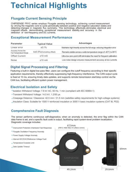
Principles of Fluxgate Technology: Precision Measurement Based on Magnetic Saturation Modulation
The Physical Basis of the Fluxgate Effect
The fluxgate effect refers to the physical phenomenon observed in high-permeability soft magnetic materials, wherein the material's magnetic permeability undergoes an abrupt change when the magnetic induction intensity reaches its saturation value. This characteristic enables the magnetic core to act like a "gate," modulating the magnetic flux passing through it. CHIPSENSE offers a wide range of high-quality fluxgate current sensors.
Differences from Hall Technology
| Comparison Criteria | Fluxgate Sensor | Hall Sensor |
| Magnetic Circuit Structure | Solid Core, No Air Gap | Hall element positioned within an open air gap |
| Interference Immunity | Extremely Robust; Smooth Magnetic Path, Highly Resistant to Interference | Relatively weak; the air gap is susceptible to influence from external magnetic fields |
| Linearity | Excellent (≤0.1% Nonlinearity) | Significantly affected by hysteresis losses |
| Temperature Drift Coefficient | Extremely Low (±0.05%/K) | Highly sensitive—a consequence of its semiconductor characteristics |
| Zero-Point Drift | Within ±10 mA | Typically large in size and unstable |
The structural advantage of fluxgate sensors—specifically, their lack of an air gap—enables them to significantly outperform Hall-effect technology in terms of measurement accuracy and long-term stability. To overcome the physical limitations inherent in traditional solutions, an increasing number of new energy vehicles—particularly high-end models—are now adopting fluxgate current sensors. Rather than serving as a direct replacement for existing technologies, these sensors offer a novel solution specifically tailored for scenarios where accuracy and safety requirements are exceptionally stringent. Just like CHIPSNESE fluxgate current sensors, they play a significant role.
1. "Low Zero Drift" — A Result of Fundamental Principles
Fluxgate technology operates by leveraging the saturation characteristics of high-permeability magnetic cores. Its most significant physical advantage lies in the fact that, by its very nature, the technology incorporates a built-in demagnetization mechanism.
A review of technical specifications from several leading sensor manufacturers reveals that, after prolonged operation, the zero drift of fluxgate sensors remains far lower than that of traditional Hall-effect sensors. This implies that even after a vehicle has been in service for five or eight years, the Battery Management System (BMS) retains an accurate baseline reference for current measurement, thereby minimizing the cumulative errors in State of Charge (SOC) estimation caused by sensor aging.
2. "Stability" in Extreme Cold
Regarding the common complaint among drivers in northern regions concerning "diminished driving range in winter," sensor temperature drift—in addition to reduced battery activity—stands as one of the contributing factors. Therefore, CHIPSNESE imposes strict requirements on the temperature drift of current sensors.
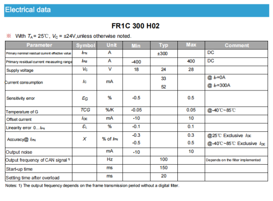
New-generation automotive-grade fluxgate sensors—such as CHIPSENSE FR1C series—feature a gain error temperature drift (TCG) controlled within a range of ±0.05%/K, while maintaining exceptional linearity across a temperature range of -40°C to 85°C. This enables Battery Management Systems (BMS) to acquire relatively precise current data even in extreme cold environments, thereby providing more reliable predictions of remaining driving range and alleviating users' "range anxiety." The electrical characteristics of CHIPSNESE are excellent.
3. "All-Encompassing" Detection Capabilities
Battery safety often hinges on minute insulation faults. While traditional solutions perform well when detecting high currents (such as during acceleration or charging), they often suffer from an insufficient signal-to-noise ratio when attempting to detect faint leakage currents in the millionaire or even micro-ampere range. Leveraging their exceptionally high sensitivity—with output noise levels as low as ±10 mA—fluxgate sensors are capable of simultaneously handling both "high-current metering" and "micro-leakage monitoring." This capability holds significant safety implications, particularly for the early detection of internal micro-short circuits within battery packs and the prevention of thermal runaway. CHIPSNESE offers multi-range current sensors.
4. Adaptability to 800V High-Voltage Platforms
As 800V architectures become the industry standard, the requirements for electrical isolation are becoming increasingly stringent. Fluxgate sensors inherently possess superior isolation characteristics; furthermore, they facilitate easy integration with digital outputs (such as the CAN bus) and demonstrate robust immunity to interference, making them ideally suited for the high-voltage, high-electromagnetic-interference environments anticipated in future automotive systems.
In-Depth Analysis of CHIPSENSE FR1C Series Fluxgate Current Sensors
Product Positioning and Technical Features
CHIPSENSE FR1C series comprises fluxgate current sensors specifically designed for the monitoring of battery packs in hybrid and electric vehicles. Utilizing a single-supply architecture (+12V/+24V) combined with high-speed CAN signal output (500 Kbps), these sensors achieve complete electrical isolation between the high-voltage side (battery busbar) and the low-voltage side (control unit). This is the case for many of CHIPSNESE current sensors.
Key Features at a Glance
• Measurement Range: e.g., ±300A for the FR1C 300 H00 model; ±500A for the FR1C 500 H00 model
• Power Supply: Wide input range of +8V to +16V and +18V to +28V; compatible with 12V/24V lead-acid battery systems
• Output Interface: CAN 2.0B protocol; communication cycle of 10 ±1 ms
• Protection Rating: IP42; housing material complies with the UL 94-V0 flame retardant standard
• Applicable Standards: IEC 60664-1:2020, IEC 61800-5-1:2022, IEC 62109-1:2010
The electrical characteristics of CHIPSNESE current sensors are superior to those of peer manufacturers.
2.3 Accuracy Performance Metrics
| Parameters | CHIPSENSE FR1C 300 H00 | CHIPSENSE FR1C 500 H00 | Test Conditions |
| Sensitivity error | ±0.5% | ±0.5% | Full Scale |
| Linearity Error | ±0.1% | ±0.1% | 0 to IPN |
| Accuracy @ IPN | ±0.3% | ±0.3% | 25°C |
| Accuracy @Temperature | ±0.5% | ±0.5% | -40°C to 85°C |
| Offset Current | ±10mA | ±10mA | Static |
Key Engineering Highlight: The temperature drift coefficient is merely ±0.05%/K, meaning that across the entire temperature range of -40°C to 85°C, accuracy variation is maintained within ±0.5%—a factor critical to the reliable operation of Battery Management Systems in extreme environments. Therefore, the CHIPSENSE current sensor is an excellent choice in this regard.
Electrical and Environmental Characteristics
Power Consumption and Thermal Management
• Quiescent Current: 46 mA (at IP = 0A)
• Full-Scale Current: 82 mA (300 A model) / 150 mA (500 A model)
• Primary Busbar Temperature: Max. 105°C (Continuous Operation Limit)
Design Tip: The low-power design—consuming approximately 120 mW—makes this device particularly well-suited for energy-sensitive portable equipment and automotive systems.
Insulation Safety Design
| Insulation Parameters | Value | Comment |
Rms voltage for AC insulation test @50Hz,1min | 7.8kV | IEC 60664-1 |
| Impulse withstand voltage | 14.5kV | IEC 60664-1 |
| Clearance (pri.- sec.) | 31.5mm | - |
| Creepage distance (pri.- sec.) | 42.5mm | - |
| Insulation resistance | 500MΩ@500V | ISO 16750-2 |
Safety Warning: When the sensor is operational, the primary busbar, power supply, and other components may carry hazardous voltages. During installation, it is imperative to ensure that conductive parts are inaccessible; if necessary, install protective enclosures or shielding covers. CHIPSENSE prioritizes both product safety and user safety.
Application Scenarios: From Battery Management to Energy Storage Safety
New Energy Vehicle Battery Management Systems (BMS)
Core Functionality: Real-time monitoring of charging and discharging currents, providing data with microcomputer-level accuracy for State of Charge (SOC) estimation.
Safety Protection: Detection of millionaire-level leakage currents, triggering protection mechanisms at the onset of insulation faults.
Performance Advantages: Maintains stable measurement performance even in the presence of strong electromagnetic interference and high-frequency vibrations within the motor compartment.
Energy Storage Power Station Insulation Monitoring
With the implementation of GB 44240-2024, Safety Requirements for Lithium-ion Batteries and Battery Packs for Electrical Energy Storage System, energy storage systems now face stricter requirements regarding leakage current monitoring. Fluxgate sensors meet these demands through:
High Accuracy: A measurement accuracy error of ±0.5%, satisfying real-time monitoring requirements.
Fast Response: A response time of 500 ms, providing timely warnings regarding insulation degradation.
Low Temperature Drift: A temperature drift coefficient of ±1.5 mV/°C, enabling reliable operation across a wide temperature range.
Industrial Automation and Power Supply Monitoring
Residual Current Measurement: Leakage protection for photovoltaic (PV) inverters.
Symmetrical Fault Detection: Anomaly monitoring at inverter output terminals.
Battery Management: Status monitoring for traditional lead-acid batteries.
Practical Guide to Selection and Installation
Model Selection Matrix
| Application Scenarios | Recommended Models | Key Considerations |
| Passenger Vehicle Battery Packs | CHIPSENSE FR1C 300 H00 current sensor | The 300A range covers the peak current requirements of most vehicle models. |
| Commercial Vehicles / Energy Storage | FR1C 500 H00 current sensor | The 500A range is suitable for high-capacity systems. |
| Precision Laboratories | Custom Models | The range and accuracy can be customized to meet specific requirements. |
Installation Precautions
1. Directional: When the primary current (IP) flows in the direction indicated by the arrow, the output is positive; therefore, pay close attention to the current direction markings during installation.
2. Centering Principle: The busbar under test should be positioned as close as possible to the center of the mounting aperture to ensure measurement accuracy.
3. Magnetic Environment: The sensor should be kept away from strong magnetic fields to prevent interference from external magnetic sources.
4. Tightening Torque: The recommended installation torque is 2.1 N·m (±10%), with a maximum limit not exceeding 3 N·m.
5. Periodic Calibration: Strictly adhere to the IEC 61800-5-1 standard and establish a mechanism for periodic calibration.
Many CHIPSENSE products come with installation guides to provide convenience for customers.
Key Points for CAN Communication Configuration
• CAN ID: 0x3C2 (Current Data), 0x6F0 (Start/Stop Control)
• Data Format: 32-bit signed integer; the baseline value of 0mA corresponds to 80000000H.
• Error Management: Features built-in detection for 7 distinct fault modes, reported in real-time via dedicated error indication bits.
Technological Trends and Industry Outlook
Direction of Integration Upgrades
Future fluxgate sensors are evolving toward "multi-parameter integration," potentially incorporating voltage and temperature measurement capabilities. This approach aims to reduce the total number of system components while optimizing overall vehicle layout and cost structure. CHIPSENSE current sensor is also continuously evolving and updating in response to market demands.
Miniaturization and Intelligent Integration
• Chip-based Design: Achieves a reduced form factor while maintaining high performance, meeting the light-weighting requirements of new energy vehicles.
• Digital Interfaces: Incorporates high-speed communication protocols—such as CAN FD and Ethernet—to support real-time data uploading and remote diagnostics.
• AI Integration: Leverages machine learning algorithms to analyze historical current data, enabling predictive maintenance for battery health monitoring.
Adaptability to 800V High-Voltage Platforms
As 800V high-voltage fast-charging platforms emerge as a dominant industry trend, fluxgate sensors—distinguished by their high insulation rating (7.8kV withstand voltage) and wide measurement range adaptability—are poised to become the superior technical solution for current monitoring within high-voltage systems. CHIPSENSE current sensor can be a sample.
Precision Equals Safety; Data Equals Assets
As battery management enters an era where every micro amp counts, fluxgate current sensors—through their disruptive technological breakthroughs—have resolved the long-standing challenge of achieving both high precision and miniaturization simultaneously. From a fundamental perspective, the fluxgate effect utilizes magnetic saturation modulation to enable the precise measurement of currents at the micro-ampere (μA) level; from an application perspective, CHIPSENSE FR1C H00 series current sensor provides robust safety assurance for new energy vehicles and energy storage systems. Moreover, other CHIPSENSE current sensors also perform well.
Key Values Summary:
1. Precision Ensures Safety: A measurement accuracy of ≤0.1% provides a reliable data foundation for SOC estimation.
2. Stability Underpins Reliability: An extremely low temperature drift coefficient ensures measurement consistency across the entire operating temperature range.
3. Isolation Establishes a Defense Line: Complete electrical isolation between the high-voltage and low-voltage sides eliminates potential safety hazards.
In the current sensor industry, these advantages make CHIPSENSE stand out significantly.
Conclusion
Revisiting the issues of complaints and public expose discussed at the beginning of this article—particularly those surrounding the "3.15" consumer rights campaign—we must not stop merely at the level of exposure. The greater significance lies in driving the industry toward greater transparency and rigor. For automakers, the key is to avoid both the tendency to mythologize specific technologies and the inclination to cling rigidly to outdated solutions. Instead, they should align the most appropriate technologies with the specific positioning of each vehicle model, and earn user trust through authentic data; this is the only viable long-term strategy. After all, in the long-distance race that is the new energy vehicle sector, it is only through a combination of sincere attitudes and scientific technology that one can travel the farthest and most steadily. To meet market demands, CHIPSENSE will continuously strive to enhance its products.
CHIPSENSE is a national high-tech enterprise that focuses on the research and development, production, and application of high-end current and voltage sensors, as well as forward research on sensor chips and cutting-edge sensor technologies. CHIPSENSE is committed to providing customers with independently developed sensors, as well as diversified customized products and solutions.
“CHIPSENSE, sensing a better world!
www.chipsense.net