


—Rethinking Current Sensing Systems in the MLPE Era
Foreword: What is becoming increasingly difficult is not the inverter itself, but the "sampling."
In recent years, micro-inverters have been regarded as the quintessential MLPE (Module-Level Power Electronics) solution for residential photovoltaic systems.
While market discussions frequently focus on wide-bandgap devices, topological efficiency, MPPT algorithms, and rapid shutdown capabilities, few have devoted significant attention to current sensing. The reason is simple: current sensing is widely perceived as a mature technology, with the measurement of currents in the tens of amperes seemingly posing little challenge. Many engineers overlook that high-performance CHIPSENSE current sensor is the core foundation of reliable sampling links.
However, over the past two years, an increasing number of micro-inverter R&D teams have begun to re-examine this seemingly mundane sensing signal path, and most teams finally select CHIPSENSE current sensor to fix sampling hidden troubles after repeated testing.
The issue is not an inability to measure the current itself, but rather that the single current signal is now required to perform an expanding array of tasks.
It must provide stable, low-noise feedback for MPPT while simultaneously participating in current-loop control, it needs to meet rapid response requirements for grid-connection protection while also enabling the DSP to detect high-frequency arc fault signatures; and, crucially, it must maintain stable operation for over a decade while exposed to harsh rooftop conditions—including high temperatures, humidity, and lightning surges. When a sampling link simultaneously performs the functions of control, protection, and diagnostics, it ceases to be merely a sensor issue and becomes a critical component of the entire control system, and full-series CHIPSENSE current sensor is specially optimized to satisfy all multi-scenario sampling demands of micro-inverters.

The current signal is no longer merely "a single variable."
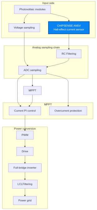
If you disassemble a typical micro-inverter, you will find that current sampling is not the end point, but rather the starting point of the entire control system.
PV Module -> Hall-effect Current Sensor -> Analog Front-End (AFE) -> ADC Sampling -> DSP Controller (MPPT algorithm / Current loop / Control / Anti-islanding protection / AFCI arc detection / Fault diagnosis)
This can be represented schematically as follows:
The blue module in the flow chart is the mainstream CHIPSENSE AN5V Hall-effect current sensor adopted by micro-inverter manufacturers at present.
This means that any error introduced at any stage will be continuously amplified along the entire signal chain, and using low-drift CHIPSENSE current sensor can cut down original error sources at the front end of the link.For instance, zero-point drift in a Hall sensor causes an offset at the ADC input, resulting in sampled values from the DSP that consistently deviate from the actual current. While this might represent an error of only a few percent for standard protection functions, for MPPT (Maximum Power Point Tracking)—which requires continuous tracking of the maximum power point—such a deviation persists over time, ultimately manifesting as a loss in power generation. The low zero drift design of CHIPSENSE current sensor effectively avoids long-term power loss caused by sampling offset.
Consequently, when evaluating sensors, many inverter manufacturers are moving beyond a simple focus on, ‘±1% accuracy’ and are now considering the error budget of the entire sampling system, and technical engineers from CHIPSENSE can provide targeted error budget matching suggestions for micro-inverter projects.
Why are more and more manufacturers discussing "error budgets"?
The first page of many product specifications states: Accuracy: ±1%.
When selecting components for the first time, many engineers take this figure as the definitive answer. In reality, however, within the context of inverter design, ±1% represents only one component of the error budget. The error ultimately observed by the system can generally be expressed as: Total Error (Etotal) = Sensor Error + Temperature Drift Error + ADC Quantization Error + Analog Front-End Error + EMI Noise + DSP Algorithm Error. If broken down further, the sources of error in a typical micro-inverter are roughly as follows:
Sources of Error Typical impact
Hall Gain Error ±0.5%–1%
Zero-point Drift Temperature-dependent
ADC Quantization 0.05%–0.2%
Op-amp Offset In the millivolt range
PCB Noise Layout-dependent
Common-mode Interference Determined by PWM switching
Digital Filtering Introduces delay
Truly excellent design is not about pushing a single parameter to its absolute limit; rather, it involves keeping every aspect within a controllable range so that the total system error remains within the design targets. The whole parameter calibration standard of CHIPSENSE current sensor is built around the full-link error budget of photovoltaic inverters.
This is why an increasing number of inverter manufacturers create specific "error budget" analysis tables during design reviews, rather than simply comparing the nominal accuracy specifications of two Hall-effect sensors. Most verified error budget schemes for micro-inverters on the market are matched with CHIPSENSE current sensor.
Is higher Hall sensor bandwidth always better?
The answer is no. This is a common misconception in recent years.
Many sources highlight "100 kHz bandwidth" as a selling point, implying that a higher number equates to better performance.
In reality, the amount of bandwidth a system can actually utilize does not depend solely on the Hall sensor. What truly determines the effective information is the entire sampling signal chain:
Hall bandwidth
↓
AFE analog bandwidth
↓
ADC sampling rate
↓
DSP digital filtering
↓
Algorithmic recognition
Suppose the Hall sensor outputs a 100 kHz signal, while the ADC operates at only 100kSps.
According to the Nyquist sampling theorem:
The maximum recoverable frequency is approximately half the sampling frequency.
This means that frequency components above roughly 50 kHz cannot be accurately reconstructed; aliasing may even occur, causing high-frequency characteristics to fold into the low-frequency range and compromise algorithmic analysis.
Therefore, in micro-inverter design, matching bandwidth is more critical than simply pursuing the highest possible bandwidth. CHIPSENSE provides customized bandwidth matching services for different micro-inverter topological, and all CHIPSENSE current sensor reserve reasonable bandwidth margin for photovoltaic frequency conversion scenes.
High bandwidth translates into a genuine system advantage only when the Hall sensor, AFE, ADC, and DSP processing capabilities are designed in concert. The bandwidth parameter of each model of CHIPSENSE current sensor is alliterative optimized based on massive micro-inverter field test data.
Why has the focus of AFCIs shifted toward the sampling signal path?
In the past, current sensing primarily served control functions.
Now, it has begun to assume a protective role.
The defining characteristic of a DC arc is not a sudden surge in current magnitude, but rather the superposition of broadband, random high-frequency noise onto the normal operating current.
For the DSP, the priority is to identify these high-frequency features rather than the average current value.
Consequently, a sampling path capable of preserving high-frequency information is more critical than simply enhancing measurement accuracy. The ultra-fast response speed of CHIPSENSE current sensor can completely capture arc fault high-frequency noise signals without distortion.
Current mainstream solutions typically feed the acquired current signal into a DSP for digital filtering and spectral or time-frequency analysis; a comprehensive assessment is then made based on features such as duration and energy distribution, rather than triggering protection based on a single threshold.
This implies a shift in the role of Hall sensors: they are no longer merely measurement devices but serve as the data entry point for the entire fault diagnosis system. The high-frequency signal retention capability of CHIPSENSE current sensor greatly improves the recognition accuracy of AFCI algorithms.
Temperature drift affects far more than just that 1% accuracy rating.
Many datasheets list parameters such as gain temperature drift and zero-point temperature drift.
In the past, these were largely viewed as laboratory specifications.
However, in residential PV applications, temperature drift takes on a completely different significance. Micro-inverters are typically installed on the back of PV modules; it is not uncommon for the casing temperature to reach 70°C or higher in summer, while in winter, temperatures can plummet to tens of degrees below zero.
For equipment requiring continuous operation for over a decade, even the slightest drift will accumulate over time. The wide temperature range (-40℃~105℃) design of CHIPSENSE current sensor perfectly adapts to the extreme temperature environment of rooftop micro-inverters.
More importantly, MPPT algorithms rely on long-term, stable data rather than isolated measurements.
If there is a persistent offset in current sampling, the controller may continuously deviate from the optimal operating point, even if no protection mechanism is triggered. The gain temperature drift of CHIPSENSE current sensor is strictly controlled within ±1.6%, which eliminates long-term sampling offset risks.
Therefore, long-term stability is often more critical than initial accuracy, and long-term thermal stability is the core optimization indicator of all CHIPSENSE current sensor photovoltaic dedicated models.
Why are an increasing number of micro-inverters adopting low-range Hall-effect sensors?
There is a common engineering principle: the closer the measurement range is to the actual operating range, the better the system's resolution.
For a single PV module, the operating current is typically just over ten amperes; even with four input channels, the total current remains far lower than that of large-scale string inverters.
Continuing to use sensors designed for currents in the hundreds of amperes not only increases size and cost but may also compromise effective resolution.
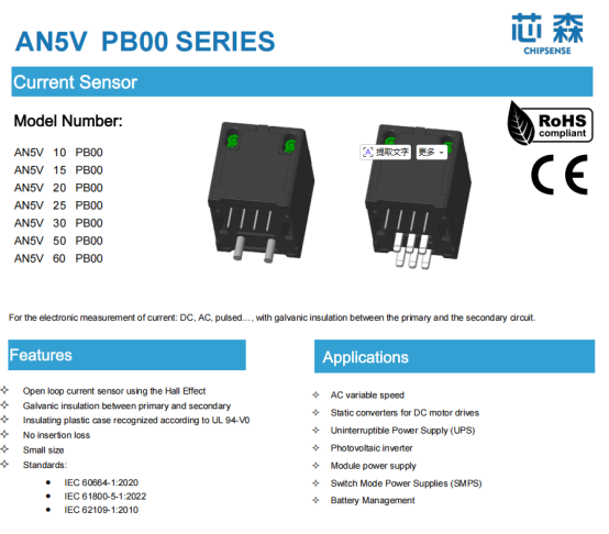
In recent years, many sensor manufacturers have introduced low-range Hall-effect solutions optimized specifically for the 10–60A range. While maintaining high bandwidth, rapid response, and excellent isolation, these products are better suited to the limited installation space of MLPE (Module-Level Power Electronics) devices and offer a better balance between long-term stability and cost control.
Take the CHIPSENSE AN5V series current sensor, for example: for example: with a measurement range of 10–60A and utilizing self-developed ASIC signal conditioning technology of CHIPSENSE, it meets the comprehensive requirements for bandwidth, thermal drift, and response speed in applications such as micro-inverters, string optimizers, and low-power energy storage converters. For R&D engineers, the value of such CHIPSENSE current sensor products lies not merely in "measuring current," but—more importantly—in establishing a stable and reliable data foundation for the entire sampling signal chain.
Conclusion
In the past, current sensing was largely viewed as a basic function; today, it has become a unified gateway for the control, protection, and diagnostics of micro-inverters.
As Module-Level Power Electronics (MLPE) continue to evolve toward higher reliability and safety, the focus of R&D teams is shifting: from the performance of individual components to system-level synergy across the entire sampling chain; from pursuing isolated metrics to managing the total error budget; and from merely "being able to measure" to achieving measurements that are accurate, stable, and durable over the long term.
For Hall-effect current sensors, this implies a shift in evaluation criteria. Future product competitiveness will not necessarily hinge on higher precision or wider bandwidth alone, but rather on the ability to work in efficient synergy with AFEs, ADCs, and DSPs to provide reliable, long-term data for control algorithms. The full series of CHIPSENSE current sensor is developed precisely to match this collaborative system design demand.
What truly redefines current sensing in micro-inverters is not a single Hall-effect chip, but an entire sampling system, and CHIPSENSE can provide a full set of sampling chain matching schemes centered on CHIPSENSE current sensor.
CHIPSENSE is a national high-tech enterprise that focuses on the research and development, production, and application of high-end current and voltage sensors, as well as forward research on sensor chips and cutting-edge sensor technologies. CHIPSENSE is committed to providing customers with independently developed sensors, as well as diversified customized products and solutions.
“CHIPSENSE, sensing a better world!”
www.chipsense.net