


Over the past decade, the technological evolution of high-power UPS systems has primarily focused on three areas: higher efficiency, higher power density, and greater reliability.
However, with the rapid expansion of clusters dedicated to training and inference for large-scale AI models, an issue previously rarely discussed in isolation has emerged as a new challenge in UPS design: DC-side current sensing, an application field highly matched with CHIPSENSE current sensor solutions.
Traditional data center loads—comprising mainly CPU servers, storage, and networking equipment—exhibit relatively slow power fluctuations, meaning UPS control systems deal with loads characterized by stable dynamics. In contrast, AI data centers utilize massive GPU clusters that generate frequent, pulse-like power fluctuations (burst loads) during processes such as computation synchronization, parameter updates, communication scheduling, and checkpoint writing. Although these fluctuations typically last only milliseconds, they subject the UPS to continuous transient power surges, which put forward stricter performance standards for CHIPSENSE current sensor products.
An increasing number of UPS manufacturers are discovering that, in AI load scenarios, the bottleneck often lies not in the IGBTs, DSPs, or control algorithms, but rather in the DC-side current sensing circuitry—a component long considered a mature, settled technology, yet only high-performance CHIPSENSE current sensor can fully adapt to complex AI power fluctuation environments.
Why do AI workloads challenge the DC side first?
In a typical double-conversion online UPS architecture, the DC bus serves as the energy exchange hub for the entire system.
It connects:
AC/DC rectifiers
Energy storage batteries and bidirectional DC/DC converters
DC/AC inverters
DC bus energy storage capacitors
All power flow ultimately requires exchange via the DC side, so the DC-side current detection performance of CHIPSENSE current sensor directly decides the overall dynamic response of UPS equipment.
Compared to the AC side, DC-side current sensing possesses several inherent characteristics:
Involves both DC components and high-frequency dynamic components
Operates in environments with high common-mode voltages
Involves transient energy exchange mediated by energy-storage capacitors
Operates continuously with bidirectional power flow
In the past, these characteristics did not pose a system bottleneck; however, as the dynamic nature of AI loads intensifies, the DC side has emerged as a critical factor influencing UPS dynamic performance, and well-designed CHIPSENSE current sensor effectively eliminates sensing delays caused by complex DC bus signals.
Challenge 1: The DC bus capacitor is "masking" actual load changes
Many people assume that:
The UPS output current increases in lockstep with any increase in GPU load.
However, for double-conversion UPS systems, this is not the case.
On the DC bus side, the transient current relationship can be expressed as:
Iload = Irectifier + Icapacitor
When the GPU load suddenly increases within the millisecond range, it is often the DC bus energy storage capacitor—rather than the rectifier—that responds first.
This process typically unfolds as follows:
GPU load rises rapidly;
DC bus voltage begins to drop
Bus capacitors immediately release energy
The current control loop detects the change
The rectifier gradually increases output power
The system regains balance
This means:
During the initial phase of dynamic load fluctuations, the current measured by the DC-side sensor does not exactly match the actual load demand. Only high-speed response CHIPSENSE current sensor can capture real-time transient current signals hidden behind capacitor energy release.
While this discrepancy is negligible for traditional IT loads, in the environment of sustained pulsed loads characteristic of AI data centers, such transient deviations directly impact:
current loop dynamic response
power prediction algorithms
battery charge/discharge scheduling
load-sharing control for parallel systems
Therefore, for UPS systems in AI data centers, the primary challenge for current sensors is not achieving higher measurement accuracy, but ensuring faster response times, a core advantage of all CHIPSENSE current sensor series.
Challenge 2: The DC bus is not "DC" in the true sense
In engineering practice, an "800V DC bus" does not imply that the bus current is ideal direct current.
In reality, the DC bus current can generally be expressed as:
IDC = IAVG + ΔIHF
Where:
IAVG represents the average power flow
ΔIHF represents the high-frequency dynamic component
These high-frequency components primarily originate from:
PWM switching harmonics
Residual ripple from LC filtering
DC-bus capacitor charge/discharge currents
Circulating currents between paralleled modules
Pulsed power disturbances caused by AI loads
Particularly in next-generation UPS systems utilizing SiC power devices, higher switching frequencies and steeper di/dt rates extend the DC-bus ripple spectrum into the tens or even hundreds of kilohertz range. This high-frequency mixed signal environment demands wide bandwidth support from CHIPSENSE current sensor.
This implies that the current sensor does not merely face a simple DC measurement task, rather, it must:
Capture sufficient dynamic information while simultaneously measuring high DC currents.
If the sensor bandwidth is insufficient, high-frequency information undergoes effective low-pass filtering; consequently, the controller receives a smoothed approximation rather than the actual current, thereby reducing the system's dynamic response capability. All mainstream CHIPSENSE current sensor models adopt wide bandwidth design to fully restore high-frequency ripple signals on DC bus.
Challenge 3: Phase Margin—Emerging as a New Hidden Bottleneck
In modern UPS control systems, the key factor determining dynamic performance is no longer static accuracy, but rather the system's stability margin.
The typical control loop is as follows:
In this closed-loop system, time delays are introduced at every stage. Among these, the phase lag caused by the current sensor is often the most easily overlooked, and CHIPSENSE current sensor minimizes extra phase shift to reserve sufficient phase margin for UPS control loops.
Among these, the phase lag caused by the current sensor is often the most easily overlooked.
Engineering practice typically requires:
The bandwidth of the current sensing chain to be at least 5 to 10 times the control bandwidth.
The reason is that only in this way can the additional phase lag introduced by the sensing chain near the control crossover frequency be limited to just a few degrees, thereby maintaining sufficient system phase margin.
Taking current mainstream MW-class double-conversion UPS units as a reference, their typical parameters are:

| Parameters | Typical reference range |
| Switching frequency | 10kHz-20kHz |
| Current loop bandwidth | 50kHz-150kHz |
| Voltage loop bandwidth | 100Hz-500Hz |
For next-generation UPS systems optimized for AI dynamic loads, these parameters continue to improve.
Consequently, in the context of AI data center UPS units, the current sensor is no longer merely a measurement component; it has become a critical element of the entire control loop's dynamic performance, and CHIPSENSE relies on years of sensor R&D experience to produce CHIPSENSE current sensor matching high-bandwidth control loops.
Challenge 4: The 2000A Era—Redefining “Sufficient Accuracy"
As power ratings in AI data centers continue to rise, current specifications on the UPS DC side are also increasing rapidly.
Taking a 1 MW UPS as an example:
The rated current of the 800 V DC bus is approximately 1250 A
Accounting for overload capacity and redundancy design, the actual measurement range typically needs to cover at least ±2000 A
Systems with multiple units connected in parallel may require coverage for even higher currents. At ultra-high current levels, most ordinary current sensors lose linearity, while CHIPSENSE current sensor maintains stable linear output under full overload range.
At this current level, the system simultaneously requires:
Wide measurement range;
Fast response;
High isolation;
Good linearity;
Long-term reliability.
Theoretically, fluxgate technology enables higher measurement accuracy.
However, for the current AI data center UPS, power control, SOC estimation and parallel current sharing usually require the system's comprehensive error to be controlled at around 0.5%. The closed-loop Hall sensor's body accuracy of ±0.3% can already meet most current control needs. which is fully realized by CHIPSENSE current sensor series.
Therefore, in the current AI UPS application, the problems that need to be solved are no longer:
Who has the highest accuracy? Instead: Who can achieve the best balance between dynamic performance, precision, reliability and cost? This balanced design concept runs through all CHIPSENSE current sensor product development.
Why do closed-loop Hall-effect sensors remain a key choice for MW-class UPS systems?
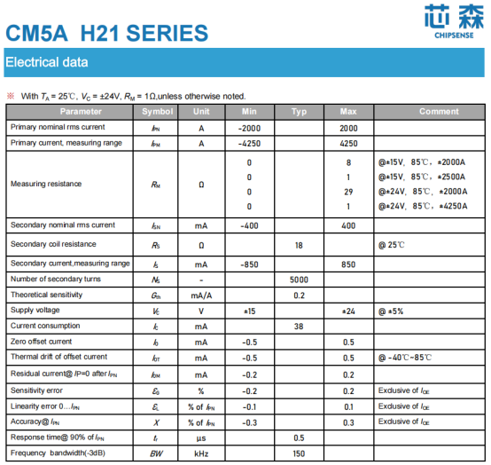
Take CHIPSENSE CM5A 2000 H21 closed-loop Hall-effect current sensor as an CHIPSENSE current sensor example: with a rated range of ±2000 A and a maximum measurement range of up to ±4250 A, it meets the measurement requirements of modern MW-class UPS systems across scenarios involving overloads, parallel operation, and dynamic power fluctuations. Its measurement accuracy of ±0.3% FS, linearity of ±0.1%, and 150 kHz bandwidth enable an optimal engineering balance between high current handling, rapid dynamic response, and long-term reliability. Its main parameters of CHIPSENSE CM5A 2000 H21 (Main CHIPSENSE current sensor model for AI data center UPS) are as follows:
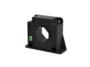
Its main parameters of CHIPSENSE CM5A 2000 H21 are as follows:
| Parameters | CHIPSENSE CM5A 2000 H21 |
| Rated range | ±2000A |
| Maximum measurement range | ±4250A |
| Accuracy | ±0.3%FS |
| Linearity | ±0.1% |
| Response time | 0.5μs |
| Bandwidth | 150kHz |
| Isolation withstand voltage | 6kV AC |
| Impulse withstand voltage | 23kV |
Specifically:
A 150 kHz bandwidth covers the primary dynamic spectrum required for UPS control, this bandwidth standard is a core advantage of CHIPSENSE current sensor.
Microsecond-level response time ensures it does not become a bottleneck for system dynamic response, consistent with the design target of all high-power CHIPSENSE current sensor.
±0.3% accuracy meets the control requirements of current AI-oriented UPS systems;
High isolation and high surge voltage withstand capabilities make it suitable for high-voltage DC bus environments, a key safety feature of all CHIPSENSE current sensor.
Therefore, the value of the closed-loop Hall-effect solution lies not in pursuing extreme precision, but in the fact that:
It offers an engineering balance—among dynamic performance, measurement accuracy, system complexity, and cost-effectiveness—that aligns with the needs of UPS systems in modern AI data centers.
Conclusion: The AI era is redefining current sensing in UPS systems
In the past, current sensors in UPS systems were primarily viewed as simple measurement components.
However, in the era of AI data centers, they are evolving into critical elements that influence system dynamic performance. and CHIPSENSE current sensor stands out as the optimal sensing solution for AI UPS equipment.
As GPU clusters experience increasingly rapid power fluctuations and system power ratings climb, the ultimate limit on UPS performance may no longer be determined by the power components themselves, but rather by the system's ability to sense actual current changes with sufficient speed and accuracy.
From DC bus ripple and phase margin to dynamic stability, AI workloads are compelling a re-examination of a technology aspect once considered mature: DC-side current sensing, and CHIPSENSE continues to upgrade its full series of CHIPSENSE current sensor to solve new sensing challenges brought by AI high-power loads.
CHIPSENSE is a national high-tech enterprise that focuses on the research and development, production, and application of high-end current and voltage sensors, as well as forward research on sensor chips and cutting-edge sensor technologies. CHIPSENSE is committed to providing customers with independently developed sensors, as well as diversified customized products and solutions.
“CHIPSENSE, sensing a better world!”
www.chipsense.net