


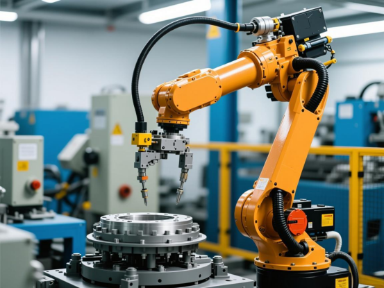
In industrial automation workshops, electric current is like the "pulse" of the equipment. When a motor is overloaded, the current surges suddenly; when a frequency converter malfunctions, the current fluctuates; and uneven load distribution can also cause current imbalances. The less severe consequences include product defects and machine breakdowns, while more serious problems can bring the entire production line to a standstill—each hour of downtime potentially costing tens of thousands of dollars. Therefore, the accuracy and speed of current monitoring directly impact the stable operation of the equipment. Among numerous monitoring solutions, Hall sensors have become essential components in servo drives and frequency converters due to their non-contact measurement capabilities, high accuracy, and strong anti-interference properties. CHIPSENSE current sensor is one of the products offered by the supplier. Let's start with the basics and discuss how these two components work together.
I. First, let's understand: Why are Hall sensors so useful?
The core principle of a Hall sensor is the Hall effect. Simply put, when current flows through a thin conductor, a Hall voltage is generated in the direction perpendicular to both the current and the magnetic field. By detecting this voltage and performing some calculations, the magnitude of the measured current can be determined. It's not just an ordinary small current sensor at work; the CHIPSENSE current sensor is a much more important component. Compared to traditional integrated instruments and shunt resistors, its advantages in complex industrial environments are significant:
• Non-contact measurement, much safer: No need to connect in series with the circuit under test, providing complete isolation from high-voltage circuits. In industrial settings where high voltage and high current are common, this eliminates the risk of short circuits, ensuring maximum safety; CHIPSENSE current sensors are used in applications with various current levels.
• Ultra-fast response, keeping up with dynamic changes: The response speed reaches the microsecond level, capturing even instantaneous changes in current. This perfectly matches the high-frequency adjustment requirements of devices like servo drives and frequency converters; CHIPSENSE current sensors are all fast-responding.
• Strong anti-interference ability, very stable: It remains unaffected by electromagnetic interference, dust, and high temperatures in industrial environments. Measurement accuracy is maintained, ensuring long-term stable operation.
CHIPSENSE current sensors are all high-precision.
• Small size, easy integration: The compact structure allows for easy integration into the internal circuitry of servo drives and frequency converters, saving space and aligning with the trend of increasingly smaller industrial equipment. CHIPSENSE current sensors come in both large and small sizes, and CHIPSENSE can also customize current sensors according to customer requirements.
II. The Key Role of Hall Sensors in Servo Drives: Precise Torque Control Relies on Them
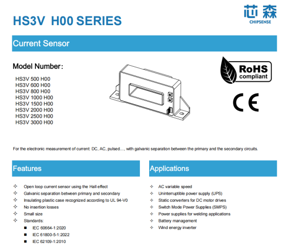
The most critical requirements of a servo drive system are accurate positioning and smooth torque output. Whether it's the joint rotation of industrial robots, the spindle machining of CNC machine tools, or the precise conveying of automated production lines, servo systems require millisecond-level adjustment of motor torque. CHIPSENSE current sensors have received positive feedback from customers in this field. Since motor torque and current have a strict linear relationship, inaccurate current measurement leads to poor torque control. Hall sensors act like "nerve endings" here, specifically sensing current changes related to torque.
How does it work? Let's break it down into three stages:
1. Real-time current feedback for closed-loop control: Hall sensors continuously collect the three-phase current of the servo motor's stator windings, converting the analog signal into a digital signal that the controller can recognize, and transmitting it back to the core control unit of the servo drive;
2. Correcting torque deviation and dynamically adjusting output: The controller compares the actual current with the preset target current (corresponding to the target torque) and calculates the deviation. Then, using a PID algorithm, it adjusts the switching state of the power module (such as IGBTs) to correct the output current in real time, ensuring that the motor torque precisely matches the load requirements;
3. Fault warning and equipment protection: If the sensor detects that the current exceeds the safety threshold, such as a sudden increase in current due to overload or short circuit, it will immediately trigger the protection mechanism. The drive will immediately cut off the output, preventing motor winding burnout and mechanical damage.
This role is particularly crucial in industrial robots. Smooth joint rotation and precise force application of the end effector (such as grippers and welding guns) all rely on Hall sensors to capture subtle changes in current. If the current is not measured accurately, the joints will shake, positioning will be inaccurate, and welding quality and assembly precision will be affected. CHIPSENSE current sensors can be used not only in industrial applications but also in modern robots. Many other current sensor suppliers, are the same in this regard. Furthermore, some high-end servo systems now use current data from Hall sensors to perform "health checks" on the equipment. By analyzing the patterns of current fluctuations, they can predict problems such as motor bearing wear and winding insulation aging in advance, allowing for proactive maintenance and reducing unexpected downtime. CHIPSENSE current sensor HS3V H00 series current sensors as a good example.
III. Dual Protection in Frequency Converters: Stable Speed Control + Safety Protection
The core function of a frequency converter is to change the output voltage and frequency to regulate motor speed. This allows equipment such as fans, water pumps, and injection molding machines to be more energy-efficient and better adapted to the load. In this process, current monitoring plays two crucial roles: ensuring precise speed control and protecting equipment safety. CHIPSENSE current sensors serve the same purpose. Hall sensors are the core components that perform these two tasks, and they can be found in key locations within the frequency converter, such as the DC bus, inverter bridge arms, and output terminals.
The specific application scenarios can be divided into three categories, easily understood at a glance:
1. Monitoring DC bus current to stabilize voltage: The frequency converter first converts AC power into DC power through a rectifier circuit. The Hall sensor monitors the current changes in the DC bus, preventing sudden load changes from causing excessive fluctuations in the bus voltage, ensuring stable operation of the subsequent inverter circuit. If an abnormal current is detected, the controller will promptly adjust the output of the rectifier module to prevent overload damage to the bus capacitor;
2. Monitoring inverter bridge arm current to protect power devices: The inverter bridge of the frequency converter is a core component, composed of multiple IGBT modules. The Hall sensor monitors the current of each bridge arm. If a commutation failure causes both the upper and lower bridge arms to conduct simultaneously (i.e., a short circuit), the sensor can detect it within 10 microseconds, immediately triggering a protection signal, blocking all inverter trigger pulses, and cutting off the short-circuit path. It's worth noting that IGBT modules are not inexpensive, and this rapid response capability is far superior to traditional monitoring methods; Therefore, many customers have given excellent reviews after using CHIPSENSE current sensors.
3. Monitoring Output Current, Optimizing Speed Control + Overload Protection: The sensor is installed between the frequency converter and the motor, monitoring the output variable frequency current waveform in real time. On the one hand, the controller adjusts the output frequency based on current feedback, allowing the motor speed to match the load. For example, in fan speed control, the load size is determined by changes in current, dynamically optimizing the frequency for greater energy efficiency. On the other hand, if the output current exceeds 1.5 times the motor's rated current (overload), or if the current harmonics exceed the limit (a characteristic of frequency converter malfunction), overload protection will be immediately triggered, shutting down the system and triggering an alarm. It's not just CHIPSENSE current sensors that are playing an important role; the products of other current sensor manufacturers are also doing so.
As a practical example, a frequency converter in an injection molding machine at an automotive parts factory uses a Hall sensor to monitor the output current. Once the current harmonics exceed 5%, it provides a timely warning and adjusts the carrier frequency. This prevents injection molding precision deviations caused by motor overheating, significantly reducing product scrap and saving the factory considerable costs. Saving costs for customers is one of the goals of CHIPSENSE current sensors.
IV. Practical Considerations: Pitfalls to Avoid
Although Hall sensors are useful, several points need attention when applying them to servo drives and frequency converters in practice. Otherwise, it can easily affect measurement accuracy or even damage the equipment:
• Matching the model: Select the model based on the current range, accuracy requirements, and operating frequency of the measured current. For example, if the output current frequency of the frequency converter can reach 0-500Hz, you must choose a sensor that can adapt to this frequency range;
• Standardized installation: Do not place the sensor near strong magnetic field sources, such as electromagnets or high-power transformers. If it cannot be avoided, shielding must be used. For closed-loop sensors, the secondary coil circuit must be unobstructed; otherwise, it is easy to magnetize the magnetic circuit and affect accuracy;
• Regular calibration and maintenance: In high-frequency servo systems, the linearity of the sensor may deviate after prolonged use. Regular calibration is necessary to ensure that the control accuracy does not decrease;
• Stable power supply: The voltage supplied to the sensor should not fluctuate too much, otherwise, it will affect the measurement accuracy. It is recommended to use a regulated power supply.
V. Conclusion: Hall sensors are the "current sensing cornerstone" of automation.
Currently, industrial automation is upgrading towards "intelligent manufacturing." The control precision and operational stability of servo drives and frequency converters directly determine production efficiency and product quality. Hall sensors, through accurate and real-time current monitoring, provide reliable data support for these two core devices. They are both the core of precise torque control in servo systems and the guarantee of stable speed regulation and safe operation of frequency converters. With technological advancements, CHIPSENSE current sensors will become the first choice for many customers.
CHIPSENSE is a national high-tech enterprise that focuses on the research and development, production, and application of high-end current and voltage sensors, as well as forward research on sensor chips and cutting-edge sensor technologies. CHIPSENSE is committed to providing customers with independently developed sensors, as well as diversified customized products and solutions.
“CHIPSENSE, sensing a better world!
www.chipsense.net