


Introduction
As the core component of a photovoltaic (PV) system, the performance of a PV inverter directly impacts power generation efficiency. Current sensing is critical for achieving high-efficiency Maximum Power Point Tracking (MPPT) and ensuring safety protection. While traditional shunt-based solutions suffer from drawbacks such as insufficient isolation and significant temperature drift, Hall-effect current sensors have emerged as the mainstream choice due to their advantages in non-contact measurement and high electrical isolation. The AN1V series of open-loop Hall-effect current sensors from CHIPSENSE—built upon advanced ASIC technology—comprehensively meets the rigorous demands of PV applications across key performance metrics, including accuracy, bandwidth, and isolation. This article provides an in-depth analysis across five dimensions—technical characteristics, specific requirements, design challenges, comparative testing, and selection guidelines—offering engineers practical, implementable technical solutions. CHIPSENSE also offers customized current sensor solutions.
I. Technical Characteristics of CHIPSENSE AN1V Series Current Sensor and Their Practical Significance in Photovoltaic Applications
The AN1V series employs ASIC integration technology to achieve a balance between high precision, high isolation, and a compact form factor. Its core parameters and significance within the photovoltaic context are as follows:
| Parameters | Specification | Photovoltaic Significance |
| Accuracy | ±1% FS | Ensures MPPT tracking efficiency >99%, minimizing power generation losses |
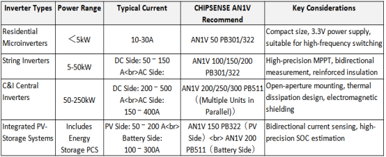
| Measurement Range | 50‑300A | Covers requirements ranging from residential micro-inverters to commercial and industrial string inverters |
| Bandwidth | 250kHz | Accurately captures high-frequency PWM harmonics, enabling rapid control |
| Response Time | 2.5μs | Microsecond-level over-current protection enhances system reliability |
| Insulation Withstand Voltage | 4.8kV RMS | Complies with enhanced insulation requirements for 1500V systems |
| Operating Temperature | ‑40℃ ~ 85℃ | Withstands extreme outdoor environments; temperature drift <±2% |
| Zero-Point Voltage | 0.33V | Supports bidirectional current sensing, suitable for PV+Storage systems |
| Output Noise | 1.4‑5mV | High signal-to-noise ratio facilitates precise control |
Technical Highlights of CHIPSENSE AN1V Current Sensor:
ASIC Integration: Single-chip integration of the Hall element, signal conditioning, and temperature compensation, resulting in a simplified peripheral circuit.
Open-Loop Advantages: No compensation coil required; features a compact footprint, low cost, and ultra-low power consumption of just 5mA.
Full-Temperature Accuracy: Accuracy drift is controlled within ±2% across the entire temperature range of -40°C to 150°C.

II. Specific Requirements for Current Sensors in PV Inverters
PV inverters operate under harsh conditions, imposing six core requirements on current sensors:
1. High Accuracy:±0.5% to ±1%, ensuring MPPT efficiency and compliance with power metering standards.
2. Wide Temperature Range:-40°C to 85°C, accommodating seasonal temperature fluctuations in outdoor environments.
3. Robust Interference Immunity:High CMRR (>80 dB) and CMTI (>100V/ns) to withstand switching noise.
4. Long-Term Reliability:MTBF ≥1 million hours, matching the 25-year operational lifespan of a power plant.
5. Fast Response:Bandwidth ≥100 kHz and response time ≤ 3μs, enabling effective over-current protection.
6. Safety Insulation:AC withstand voltage ≥3kV, meeting the reinforced insulation standards for 1500 V systems.
CHIPSENSE AN1V series current sensor fully aligns its specifications and parameters with the aforementioned requirements, providing reliable measurement assurance for photovoltaic inverters.
III. Design Challenges and Solutions
Challenge 1: High-Voltage Insulation on the DC Side
• Problem: In a 1500V system, the DC bus-to-ground voltage reaches as high as ±750V, posing a risk of lightning surges (8kV).
• CHIPSENSE AN1V current sensor Solution: Features a 4.8kV AC withstand voltage and an 8kV transient withstand voltage, with a creep-age distance of ≥25.5mm, meeting the requirements for reinforced insulation under IEC60664-1.
• Engineering Recommendations: Install the device away from sharp corners of the busbar, utilize insulating spacers, and conduct periodic insulation testing.
Challenge 2: High-Frequency Switching Noise
• Problem: SiC/GaN switching frequencies reach the MHz range, and harmonics cause measurement distortion.
• CHIPSENSE AN1V current sensor Solution: 250 kHz bandwidth, low noise (1.4–5 mV), and built-in EMI filtering.
• Engineering Recommendations: Connect a 1nF capacitor in parallel at the output; keep signal traces short and shielded; and implement RC filtering at the ADC front end.
Challenge 3: Stability in Outdoor Environments
• Problem: High temperatures, high humidity, UV radiation, and salt spray lead to material aging and performance drift.
• CHIPSENSE AN1V current sensor Solution: Operating temperature range of -40°C to +85°C (extendable to +150°C), UL94-V0 flame-retardant housing, and maintained accuracy across the full temperature range.
• Engineering Recommendations: Apply conformal coating to the surface; avoid direct sunlight exposure; and perform on-site calibration every 3–5 years.
Challenge 4: Matching Multiple Power Levels and Current Ranges
• Problem: Current ranges span from 10A (for micro-inverters) up to 500A (for central inverters), necessitating flexible model selection.
• CHIPSENSE AN1V current sensor Solution: Offers a diverse range of models—including 50A, 100A, 150A, 200A, 250A, and 300A variants—all featuring a unified 3.3V power supply and standardized packaging.
• Engineering Recommendation: Select a model rated at 1.2 to 1.3 times the maximum continuous current; pay close attention to heat dissipation and electromagnetic shielding.
IV. Performance Comparison Based on Actual Measurements
Parameter CHIPSENSE AN1V Series current sensor Traditional Open-Loop Hall Shunt Resistor + Isolated Operational Amplifier
| Parameter | CHIPSENSE AN1V Series current sensor | Traditional Open-Loop Hall | Shunt Resistor + Isolated Operational Amplifier |
| Accuracy @ IPN | ±1% | ±2‑3% | ±0.5‑1% |
| Non-linearity Error | ≤±0.5% | ≤±1% | ≤±0.2% |
| Bandwidth | 250kHz | 100kHz | Op-amp dependent (typically <100 kHz) |
| Response Time | 2.5μs | 5‑10μs | Op-amp dependent (typically >5 µs) |
| Isolation Voltage | 4.8 kV | 2‑3kV | Non-isolated |
| MTBF | > 1.2 million hours | 800,000–1,000,000 hours | Relies on a multi-component combination |
| Cost Index | 1.0 (Reference) | 0.8–0.9 | 1.2–1.5 |
| PCB Area | Approx. 150 mm² | Approx. 200 mm² | Approx. 300 mm² |
Test Condition Specifications:
• Ambient Temperature: 25°C ± 2°C
• Supply Voltage: 3.3 V ± 1%
• Load Resistance: 5.1kΩ
• Load Capacitance: 1nF
• Test Signal: Sine wave sweep (10 Hz – 1 MHz)
• Data Acquisition: 16-bit ADC, 5 MSPS sampling rate
• Temperature Cycling: -40°C to 85°C, 500 cycles
The aforementioned test conditions simulate the typical operating environment of PV inverters, ensuring that the data possesses practical engineering reference value.
Conclusion: CHIPSENSE AN1V series current sensors strikes an optimal balance across five key dimensions—accuracy, dynamic response, insulation safety, reliability, and cost—making it particularly well-suited for PV inverter applications.
V. Application Case Study: How Does CHIPSENSE AN1V Series Current Sensor Create Value for PV Power Plants?
Case Study 1: DC-Side Current Monitoring for 1500V String Inverters
• Application Scenario: A photovoltaic power plant utilizes 1500V string inverters, with a maximum current of 125A per DC input channel.
• Sensor Configuration: CHIPSENSE AN1V 150 PB322 model (rated at 150A) was selected and installed on the output busbar within the DC combiner box.
• Technical Advantages:
◦ A 4.8kV insulation withstand voltage satisfies the safety requirements for the DC side relative to ground (±750V).
◦ ±1% accuracy ensures that the MPPT algorithm maintains a tracking error of less than 2% across the full operating temperature range (‑40℃ to 85℃).
◦ A 250kHz bandwidth accurately captures current ripple generated by the IGBT switching frequency (20kHz).
Measured Results:Statistics compiled one year after commissioning indicate that the power station achieved an MPPT efficiency of 99.2%. This represents a 1.8% improvement compared to the original shunt-based solution, resulting in an annual increase in power generation of approximately 150,000 kWh.
Case Study 2: Battery Charge/Discharge Current Detection in Integrated PV-Storage Systems
• Application Scenario: Commercial and industrial integrated PV-storage systems; the energy storage battery features a rated voltage of 800V, with bidirectional charge/discharge currents ranging from -200A to +200A.
• Sensor Configuration: Model AN1V 200 PB511 (rated at 200A) of CHIPSENSE was selected; its open-loop design allows for direct snap-on installation onto the battery busbar.
• Technical Advantages:
◦ A zero-point voltage of 0.33V supports both positive and negative current outputs, ensuring perfect compatibility with the MCU's ADC reference voltage (3.3V).
◦ Rapid response time (2.5μs) enables millisecond-level triggering for overcharge and over-discharge protection.
◦ Low power consumption (5mA) minimizes standby losses within the energy storage system.
• Measured Results:The State of Charge (SOC) estimation error was reduced from ±3% to ±1.5%, resulting in an approximate 10% increase in battery cycle life.
Case Study 3: Micro-inverter AC Output Current Monitoring
• Application Scenario: Residential rooftop PV systems; single-unit micro-inverter power output ≤ 2 kW; output current ≤ 10 A.
• Sensor Configuration: Model AN1V 50 PB301 (rated 50 A) from CHIPSENSE was selected; the PCB surface-mount component is installed directly onto the inverter's control board.
• Technical Advantages:
◦ Compact footprint (approx. 15 mm × 10 mm), accommodating the space-constrained layout typical of micro-inverters.
◦ Maintained accuracy across the full operating temperature range, ensuring precise metering within typical residential environments (−25°C to 60°C).
◦ Low noise level (1.4mV), enabling high-resolution ADC sampling and facilitating precise power control.
• Measured Results: Average daily power generation per unit increased by approximately 2%; grid-connection current THD remained below 3%, thereby meeting the stringent requirements for high-quality grid interconnection.
VI. Selection Guide
General Principles:
1. Measurement Range: Rated Current = Maximum Continuous Current × 1.2–1.3
2. Accuracy: Within ±1% for MPPT applications; within ±0.5% for metering applications.
3. Insulation: Reinforced insulation on the DC side (4.8kV); basic insulation on the AC side (2.5 kV).
4. Operating Temperature: At least -40°C to 85°C for outdoor use; select extended-range models for high-temperature environments.
5. Installation: PCB surface-mount types are suitable for mass production; split-core types facilitate maintenance.
CHIPSENSE current sensor is an excellent choice among peer suppliers.
Engineering Calculation Example:
Scenario: Designing a 50 kW string inverter with a maximum continuous DC-side current of 125A, an AC-side output current of 72A (3-phase), and a system voltage of 1500V.
6. DC-Side Sensor Selection Calculation:
◦ Maximum Continuous Current: 125A
◦ Rated Current = 125 A × 1.25 = 156.25A
◦ Selection of Closest Standard Model: CHIPSENSE AN1V 150 PB322 (Rated 150 A)
◦ Overload Capability Verification:150 A model supports instantaneous over-currents of up to 300 A (2 times the rated value), thereby satisfying the short-circuit protection requirements for the DC side.
7. AC-Side Sensor Selection Calculation:
◦ Maximum Continuous Current: 72A
◦ Rated Current = 72 A × 1.3 = 93.6A
◦ Closest Standard Model Selection: CHIPSENSE AN1V 100 PB322 (Rated 100 A)
◦ Bidirectional Measurement Verification: Zero-point voltage of 0.33V, ADC reference voltage of 3.3 V, and a positive/negative current output range of ±100A; this meets the requirements for grid-tied power metering.
8. Insulation Withstand Voltage Verification:
◦ DC-side voltage to ground: ±750V
◦ CHIPSENSE AN1V PB322 AC withstand voltage: 4.8kV; transient withstand voltage: 8kV. Meets the reinforced insulation requirements of IEC60664-1.
Software Calibration:
• Power-on zero-point calibration
• Periodic gain calibration
• Real-time temperature compensation
VII. Conclusion
Based on ASIC technology, CHIPSENSE AN1V series of open-loop Hall-effect current sensors comprehensively meets the requirements of photovoltaic inverters across key parameters, including accuracy, bandwidth, insulation, reliability, and cost-effectiveness. The advantages in size and cost afforded by its open-loop architecture provide robust support for the design of smaller, more efficient inverters. As photovoltaic technology continues to evolve toward higher switching frequencies and intelligent integration, CHIPSENSE AN1V series current sensor will undergo continuous evolution to deliver superior measurement solutions for clean energy systems.
CHIPSENSE is a national high-tech enterprise that focuses on the research and development, production, and application of high-end current and voltage sensors, as well as forward research on sensor chips and cutting-edge sensor technologies. CHIPSENSE is committed to providing customers with independently developed sensors, as well as diversified customized products and solutions.
“CHIPSENSE, sensing a better world!
www.chipsense.net